Assembly Rules
Assembling a milling table with your own hands should be done in stages.
First you need to decide on the tabletop and make a hole in it for the tool. Next, material supply control systems are attached. The milling machine itself must be firmly secured under the tabletop. It should not dangle or hang; any movements can lead to injury during operation or equipment breakdown. It is better to fix it with self-tapping screws, for your own peace of mind.
Next, install the bed. It is very firmly attached to the tabletop to withstand all loads and vibrations. You can make a milling table with legs, but you should take care of their thickness and fastenings.
Making the top clamp
When wondering how to make a home-made machine safer to use and ensure ease of processing large workpieces on it, you can equip such equipment with an upper clamp. To create this device, made on the basis of a roller, it is also necessary to prepare drawings.
A ball bearing of a suitable size is often used as a roller for the pressing device. Such a roller is mounted on a holding device that allows it to be fixed at any distance from the tabletop. With the help of this simple universal device, the workpiece of any thickness will be securely fixed when moving along the surface of the work table.
In the video below, a man shows his homemade milling table, which he assembled right on the balcony of his own house.
First make the body
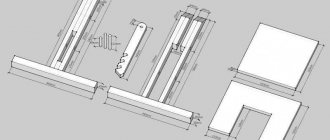
1. Cut out the side walls A. Then cut out the shelves B, partitions C, top panels D and box supports E with a 6mm allowance in length.
2. Cut grooves and folds in the side walls A and partitions C for shelves B and top panels I) (Fig. 1 and 1a).
Also cut out grooves for partitions C in the top shelf B.
Z. On both side walls A, cut folds along the rear edge on the inside for the lower and upper rear walls F, G (Fig. 1a).
4. Mark the lines of grooves for box supports E on the side walls A (Fig. 1a). Adjust the groove disc according to the thickness of the box supports and make grooves in the side walls and partitions C.
5. Taking into account possible differences in plywood thickness, saw the partitions C, top panels D and box supports E to the final length. Then cut out the base board H to the specified dimensions and sand all the plywood parts with sandpaper No. 180.
6. Place one of the side walls A on the workbench with the grooves facing up. Glue the top panel D, the two drawer supports E, and the top shelf B into place. Then add the divider C and secure the assembly with clamps (photo A).
7. When the glue has dried, glue the bottom shelf B and the base board H. Temporarily put them in place, without gluing, the second side wall A to align the parts (photo B).
8. Clamp the mounting brackets to support the second partition C. Glue the partition in place by sliding it into the groove of the top shelf B. Then add the box supports E, the top panel D, and finally the second side wall A (photo C).
9. Having specified the dimensions, cut out the lower and upper back walls F, G and set them aside. Drill 4mm holes in the top panels D to secure the cover.
Making a plate for installing a manual router on a table with your own hands
Milling plates are made independently in the following cases:
- creating a milling table with your own hands for a manual or homemade stationary router;
- further unsuitability of the industrial milling table slab.
The material chosen is:
- Sheet steel;
- aluminum plate;
- plexiglass (textolite);
- sheet phenol or carbon plastic;
- MDF;
- laminate;
- thick plywood.
The thickness of the material is selected from 4 mm to 10 mm.
The simplest model of a homemade mounting plate is a two-layer one.
Manufacturing of the supporting part:
- The bottom layer is made of durable material (steel or aluminum).
- The size of the workpiece is selected depending on the specific model of the hand router, but within the range of 200x300 - 250x350 mm.
- Holes are drilled in the corners for screws for fastening to the table.
- A hole is drilled at the intersection of the diagonals of the bottom plate.
- It expands to fit the size of the largest cutter used.
- Subsequently, the central pocket is countersunk to remove burrs.
- The standard getinaks or carbolite overlay is removed from the router.
- Along the edges of the central pocket, holes are marked and drilled for mounting the router into the mounts of the standard lining.
Making the top:
- The top plate is replaceable. Used instead of ring inserts. The material used is less durable, thinner, with a smooth surface.
- All dimensions from the base plate are transferred to the workpiece.
- Holes for fastening to the table and router are drilled with a chamfer for the heads of the mounting screws “sunk”.
- The central pocket is made to fit a specific cutter size.
- Several such plates are made to suit the diameter of the cutting tools used.
The next version of a homemade milling plate is single-layer. It uses replaceable rings to match the diameter of the cutter.
- In the middle part of the base plate, a recess is made with the diameter and thickness of replaceable ring inserts.
- Holes are drilled for fastening the rings.
- They are threaded for screws to secure the inserts.
If necessary, replacement linings are also made independently.
- Round blanks with a diameter 40–50 mm larger than the diameter of the largest cutter are cut out of thin sheet material.
- Holes are cut in the center for a specific cutting tool.
- The holes are countersunk from burrs.
- At the opposite edges of the plates, holes are drilled for fastening the rings to the base plate with a chamfer for countersunk screws.
Table design
The simplest design of a milling table involves the presence of three main elements - a working surface or tabletop, a machine base or bed, and additional equipment - a limit bar, adjustment devices, and safety devices.
Among the device layout diagrams that can be found on the Internet, all designs can be divided into three types:
- Multifunctional free-standing devices for working and storing tools.
- Tabletop small-sized tables for milling, which are installed on a workbench or desktop.
- Tables are attachments that are attached to brackets or special seats to a workbench or desktop.
Don't miss: Copy-milling machine for wood: what is it for and how to make it yourself
And if the former require a certain skill and skill for design and assembly, then desktop structures and milling attachments can be made independently from drawing development to practical implementation.
The basis of the table is the bed - a rigid structure on which the working surface of the milling table - the tabletop - is placed, there is a mount for installing the tool and equipment for fixing and adjusting it.
The entire structure is made of wood and lumber, held together with glue and screws to assemble the furniture. Structurally, a simple table for a router should be of a rigid and stable structure to dampen vibration and at the same time be lightweight so that it can be easily moved from place to place.
Manufacturing of bed and table top
The bed of a homemade milling installation must be highly stable and reliable, since it will bear the main loads. Structurally, it consists of a frame with supports on which the tabletop is fixed. As a material for the manufacture of the frame of the bed, you can use metal profiles connected by welding, chipboard, MDF, wood. It is advisable to first prepare drawings of such a device. They must indicate all structural elements and their dimensions, depending on the dimensions of the parts that are planned to be processed on such milling equipment.
Processing options with different types of cutters
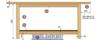
The lower part of the bed from the front side must be deepened by 100–200 mm so that nothing interferes with the feet of the milling machine operator. If you are going to process linings for doors and the ends of facades for them on your homemade machine, then the dimensions of the frame can be as follows: 900x500x1500 (height, depth, width).
One of the significant characteristics of the bed for a homemade milling machine is its height, on which the ease of working on such equipment depends. According to ergonomic requirements, the most suitable height for equipment used while standing is 850–900 mm. It is advisable to make the lower parts of the frame supports adjustable. This will make it possible not only to compensate for uneven floors, but also, if necessary, to change the height of the milling table. To make a turntable with your own hands, just fix special wheels on its legs.
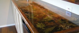
You can make a low-price, highly reliable milling table from the top of an old kitchen table. Such countertops are usually made of chipboard sheets 26 or 36 mm thick, coated with wear-resistant plastic. Their surface ensures good sliding of the workpiece, and the chipboard base perfectly dampens vibrations that occur during operation of the equipment. If you make a desktop for a machine with your own hands, then MDF and chipboard (LDSP) boards with a thickness of 16 mm or more are suitable for these purposes.
Removable tabletop manufacturing technology
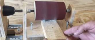
| A laminated chipboard sheet is used as a tabletop. Its thickness is 19 mm. The size is 360·540 mm. It corresponds to the size of the resulting window on the machine. Having oriented to the sides, the center is determined. The router shaft must be positioned in the center. Place the support pad in the selected location and outline the pad. |
| A contour is formed on the chipboard sheet. It is necessary to accurately cut the window along this contour. |
| To install the support pad tightly without gaps, you need to drill holes exactly along the edges of the markings. Holes are needed at all extreme points. |
| A jigsaw is used to cut out the window along the drawn contour. If there are irregularities, the walls are refined using abrasive paper and a file. |
| To install the router, you need two steel rods Ø 8 mm. Construction staples are used. You just need to saw them off using an angle grinder cutting disc to a length of 255 mm. |
| The router has holes where you can install rods. To make it easier to install them, any irregularities on the surface of the pins are removed with sandpaper. |
| Having installed the tool exactly above the window, determine the places where the rods will be located during installation. But for them you need to cut special grooves. They are milled. Preparation required for milling. |
| The guide strips are secured using pistol-type clamps. The grooves for the pins will be milled in relation to them. The depth relative to the surface is also set so that on the front of the table the support pad of the router is exactly level with the tabletop. |
| Having completed milling on one side, proceed to a similar operation for the second rod. Guide strips are also installed here and fixed in the desired position. |
| The rods must be pressed from above using clamping bars. Therefore, you will need to prepare a groove where these wooden elements will be installed. First, they are cut out and tried on in place. Then a groove of the required dimensions is marked and milled. |
| Once installed in place, the rods will be securely and tightly pressed in their grooves. |
| It can be seen that the recess under the planks was made to a shallower depth. Structurally, this is how it was originally intended. |
| The router is installed in its place. It is clearly positioned relative to the countertop used. After fixation, it will stand in a given place without the possibility of moving in any direction. |
| Since production is carried out in experimental mode, each stage is checked by preliminary assembly of structural elements. At the moment, we are checking how the wooden planks will press the rods and fix the tool in place. |
| M8 bolts will be used for fixation. They have a secret head. To simplify installation, wing nuts will be used. They are tightened without using a key. At the same time, such a solution allows you to adjust the flatness of the router sole on the front side when tightening. |
| By pressing the parts in place on the reverse side using clamps, holes are drilled. No special markings were made, therefore, to facilitate assembly, the mating fragments are marked with markers of different colors. A countersink is used to countersink holes on the working surface of the table for conical screw heads. |
| On the inside of the clamping strips, holes are drilled to Ø 15 mm. The M8 nuts will be hidden here. Additionally, an auxiliary groove is machined using a round file. It will allow you to press the rods more tightly. |
| The bolts are in place. The nuts are tightened. They will hide in the prepared holes. The assembly and disassembly process will not require much time. The bolts will always be in this position. |
| Now all the elements are easily installed in their places. No additional adjustment is needed. |
| The tabletop can be tried on the table. Therefore, it is first laid with the working surface down. You will need to turn it over to see how it fits on the machine. |
Don't miss: Vertical milling machines: device, description, video
| The revolution is easy. The tabletop is installed in its place. |
| She stood level with the main table of the table saw. If you recess the cutters, then the additional part will not interfere with the work of cutting parts. Important! The manufactured device did not in any way deteriorate the properties of the main machine on which installation was planned. |
| Cutting out the windows and milling out the auxiliary space inside the tabletop weakened it noticeably. Therefore, reinforcement will be required. To increase the strength of the manufactured attachment, it was decided to use additional bars. They are cut to the required size on a sawing machine. |
| Having cut out the longitudinal and transverse bars, they are screwed to the tabletop. They are pre-lubricated with glue and then fixed with self-tapping screws. All holes are pre-drilled with a Ø 3 mm drill and then countersinked to fit a self-tapping screw Ø 8 mm. Galvanized wood screws are used. |
| Having placed the tabletop on the machine, you can see that the rip fence will not be able to move along its guides. The design of the tabletop itself needs to be improved. |
| The surface to be removed is marked. This type of removal can be done using a router or two passes on a circular saw. |
| Having completed the preparation, the tabletop is put back in place. To make it easier to work at this stage, the router and accessories were removed from it. |
| Once the excess has been removed, the rip fence can be moved around the entire table. It was decided to use it as a clamp for milling. You will only have to slightly modify the auxiliary elements. |
Manufacturing a lift for a milling tabletop
| It is necessary to make several auxiliary elements that will help move the router up and down. The type of elevator being manufactured is shown. |
| By turning it over, you can examine the features of the device. Supports and levers are visible. We need to figure out what and how will work here. |
| The arrow indicates a fixed stand. It bears the main load from the tool. Therefore, there are special requirements for it. It should be strong enough. It will have to counteract the weight of the router, as well as the return springs that are installed on this tool. |
| This arrow points to the axis. The lever can rotate relative to it. The router itself “hangs” on this lever. |
| The design of the lever has a peculiarity. There is a radial convexity here. It rests on the part of the router where there are no ventilation holes. Additionally, it has a thickening in the plastic case, so pressure will not violate the integrity of the instrument’s structure. |
| The bar shown contains a nut. If you rotate the screw, the block will move. A bracket is placed between the lever and the block. Steel loops are installed at its ends. They allow you to adjust the dimensions of all elevator parts. |
| Another important element. It contains the head of the bolt. It rests on a bearing. Therefore, it can be rotated in any direction without much effort. |
| The main support post will be cut from plywood 20 mm thick. |
| To ensure that the stand does not move in any direction during operation, it is reinforced with additional gussets. The result is a product that resembles a rocket. All that remains is to assemble such a device. |
| The “rocket” will be installed on one side of the existing window. |
| To make the bracket, plywood with a thickness of 20 and 10 mm is used. Outer plates made of ten-millimeter plywood are screwed to the lever. The joint planes are first coated with PVA glue. |
| A bearing housing will be installed on the back side of the window. |
| Before assembly, the surfaces of the “rocket” supports are coated with glue. |
| The support legs are screwed with a long self-tapping screw (75 mm). |
| Holes for additional fasteners are drilled on the back of the tabletop. This strengthening is justified; the resistance of the router springs reaches up to 200 N (20 kg). |
| Four more screws are screwed in, the length of which is 60 mm. Attention! When installing self-tapping screws on the front side, the holes must be countersunk. |
| The block is drilled through. A Ø 10 mm drill is used. |
| Here you will need to install a drive nut. To prevent sharp edges from damaging the block itself, drill holes Ø 2.5 mm to a depth of 1.5 mm. |
| The nut is pressed into place. To do this, a block with a nut is placed between the jaws of a vice and squeezed until the nut is finally seated in place. |
| The part gets the desired look. The nut is firmly fixed to the block. The strength is sufficient for the normal operation of this element of the elevator structure. |
| To install the bolt head, you need to drill a hole with a diameter of 20 mm. Here, a socket head will be used in the future, so the hole is prepared with some margin. The drilling depth is 16 mm (19 mm thick chipboard). Important! Plywood 20 mm thick is installed underneath. Therefore, the strength of the structure will not be compromised. |
| After drilling a blind hole, a through hole is drilled. Its diameter is 8.5 mm. This is where the bearing and bolt will be installed. |
| A nut is placed between the bolt head and the bearing. A closed bearing is used, into which chips and dust cannot enter. |
| Turning the tabletop over reveals a long bolt (180 mm). It needs to be fixed so that it can rotate. |
| The washer is installed, and then the nut with the fluoroplastic insert is tightened. The installed fluoroplastic will not allow it to unwind. It does not fit tightly, there is a gap of about 0.5 mm. It will allow the bolt to rotate and transmit forces in any direction. |
| There is a gap between the end of the bolt and the lever that needs to be filled. You need a bracket and overhead hinges. |
| Regular hinges are not enough; additional strips will need to be installed. |
| The length of these strips is selected. |
| Self-tapping screws are screwed into the block. Loops will be put on them. |
| Once put on, the loop will not be able to remove itself from the screw head. The existing groove in the hinges is narrower than the hole, onto which the hardware cap is placed. |
| All that remains is to assemble the entire elevator structure. All structural elements mentioned earlier have been manufactured. |
| By installing the tabletop in the machine window, you can check the functionality of the elevator structure. A screwdriver is used, into which a 13mm socket head is installed. By starting rotations in one direction or another, the cutter moves up or down. Using a measuring tool, you can set the depth of milling grooves on parts. |
Design features of the milling table
An existing workbench can be adapted for a milling machine. But it is more expedient, to eliminate the influence of strong vibration during operation of the cutter, to make a separate structure that ensures the stability of the table.
The main loads during equipment operation are transferred to the base. Therefore, the frame must be reliable and stable. The bed is understood as a fixed base on which the router is located. It takes all the loads and is a structure in the form of a table with a fixed lid. It can be made from a metal pipe, angle, channel, wood, chipboard.
It is necessary to take into account that the router itself is attached to the tabletop from below, which means that there needs to be empty space there.
The router is attached to the table through a high-strength and rigid plate for installation work. It is preferable to make it from metal, textolite or tongue and groove board.
Don't miss: Machine vices for milling machines: requirements according to GOST
The base of the router has threaded mounting holes for mounting. If there are no threaded holes, threading is done independently. If the task is impossible, secure the milling device using special clamps.
Start the work by using a milling cutter to select the shape and thickness of the mounting plate. To make it easier, straight corners on the mounting plate must be rounded with a file. A recess in the table top ensures that the plate is positioned flush with the table top.
Make a hole in the center of the plate for the tool to exit, drill holes for attaching the plate to the table. The next step is to drill holes to attach the milling device; keep in mind that the fasteners must be countersunk.
Making a plate for installing a manual router on a table with your own hands
Milling plates are made independently in the following cases:
- creating a milling table with your own hands for a manual or homemade stationary router;
- further unsuitability of the industrial milling table slab.
The material chosen is:
- Sheet steel;
- aluminum plate;
- plexiglass (textolite);
- sheet phenol or carbon plastic;
- MDF;
- laminate;
- thick plywood.
The thickness of the material is selected from 4 mm to 10 mm.
The simplest model of a homemade mounting plate is a two-layer one.
Manufacturing of the supporting part:
- The bottom layer is made of durable material (steel or aluminum).
- The size of the workpiece is selected depending on the specific model of the hand router, but within the range of 200x300 - 250x350 mm.
- Holes are drilled in the corners for screws for fastening to the table.
- A hole is drilled at the intersection of the diagonals of the bottom plate.
- It expands to fit the size of the largest cutter used.
- Subsequently, the central pocket is countersunk to remove burrs.
- The standard getinaks or carbolite overlay is removed from the router.
- Along the edges of the central pocket, holes are marked and drilled for mounting the router into the mounts of the standard lining.
Making the top:
- The top plate is replaceable. Used instead of ring inserts. The material used is less durable, thinner, with a smooth surface.
- All dimensions from the base plate are transferred to the workpiece.
- Holes for fastening to the table and router are drilled with a chamfer for the heads of the mounting screws “sunk”.
- The central pocket is made to fit a specific cutter size.
- Several such plates are made to suit the diameter of the cutting tools used.
The next version of a homemade milling plate is single-layer. It uses replaceable rings to match the diameter of the cutter.
- In the middle part of the base plate, a recess is made with the diameter and thickness of replaceable ring inserts.
- Holes are drilled for fastening the rings.
- They are threaded for screws to secure the inserts.
If necessary, replacement linings are also made independently.
- Round blanks with a diameter 40–50 mm larger than the diameter of the largest cutter are cut out of thin sheet material.
- Holes are cut in the center for a specific cutting tool.
- The holes are countersunk from burrs.
- At the opposite edges of the plates, holes are drilled for fastening the rings to the base plate with a chamfer for countersunk screws.
Various designs
The lightest milling table is considered to be made from a chipboard sheet with a hole for the tool. A wooden guide is mounted to the table, secured with ordinary clamps. Such a design can be easily mounted on a table, installed between stools, and so on.
Craftsmen make milling tables from ordinary 15 mm plywood. The table consists of several parts. You need a lid, a couple of walls, several support bars (usually four), one long block needed to attach the router table directly to the workbench. In the case of an ordinary table, you need to hollow out grooves in the walls in advance in order to install clamps.
There is a special niche in the table top for the cutter. It is made in the shape of a semicircle. This groove can be easily made with a small hacksaw. Holes are drilled into which the mounting screws will go, as well as a movable stop mounted on the table, which is secured with bolts.
Making a table for a router yourself
It is recommended to start working on a milling table by developing a working drawing or a simple drawing of the layout of all components and parts. The task of this stage is to think through all the elements and fastening points as accurately as possible.
The main element of a homemade table for a router is the tabletop. Not only should it be as smooth as possible, it should be strong, since it is to the tabletop that the router attachment point will be attached.
The tool itself is installed under the tabletop; one of the conditions for installing the router is its vertical location. In some projects, the router mount provides for its adjustment in several planes. This version of the project can be implemented for experienced craftsmen, but in the simplest project it is enough to simply fix the tool strictly vertically.
One of the most time-consuming parts to manufacture is the router plate. A simple design with a tabletop made of multi-layer plywood or particle board will eventually develop wear in the place of the hole for the cutter. This state of affairs will not allow you to get the correct cut - the wood will not fit tightly to the surface. It’s a different matter when a plate made of a more durable material – plastic or metal – is installed here.
The plate for the router can be made of aluminum with a thickness of 4-5 mm; this is the best option for such a device. It can be replaced with thick plastic, for example, textolite
You can also use a metal plate, but in this case you need to install the cutters especially carefully and carefully
When starting to select materials, it is worth remembering that the tabletop must be strong and smooth; it is unlikely that it will be possible to make a tabletop from a set of boards, so you should immediately provide several options for materials for it - from furniture chipboard to multi-layer plywood with a laminated surface.
It is recommended to make the frame from plywood or fiberboard. This material is quite affordable and easy to process.
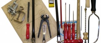
Required Tools
Considering that most of the work will be related to wood, there is no need for special tools. However, if the plate for the router is made of metal, then it is also necessary to provide a tool for working with metal. The entire set of tools might look like this:
- Wood router with a set of cutters;
- Electric drill with a set of drills for wood and metal;
- Circular saw or jigsaw;
- Screwdriver with a set of bits;
- Metal files;
- Grinder with cutting and grinding discs;
- Clamps and clamps;
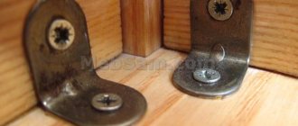
- Carpentry or furniture metal corners;
- Tape measure, square, ruler.
For gluing you will need glue and a brush. Sandpaper for sanding and finishing edges.
In order to make a durable structure, it is also necessary to prepare a workplace so that there is enough space for processing parts.
Electric drive, safety tips at work
You can assemble a functional milling table with your own hands when the master has information about the electric drive that will be used in the work. Let's consider the power parameter for choosing an electric drive:
- The power of the electric motor for small household chores can be from 500 W. It has been noted that it is sufficient for processing small workpieces when there is no need to make deep cuts.
- An electric drive with a 1.1 kW motor is considered optimal for a home milling machine.
- An electric drive with a power of 1-2 kW makes it possible to process any workpiece using different cutters. Home milling machines use electric motors: hand drills, grinders.
Important! Experts recommend that before assembling a milling machine, determine the power of the milling machine; it should not be less than 2 kW. This power allows the master to work with any wood
It is recommended to choose milling cutter models with variable speed control. The rotation speed of the router is very important for obtaining an even cut on the workpiece. If this parameter is high, the cut will be clean.
Best models
Experts believe that one of the best models of in-bench routers is the Porter Cable 7518. This version is equipped with a powerful motor. The installation platform reaches 107 mm. It is recommended to buy such a device with a fixed base - the difference in price is small, but the practical benefits are very noticeable. If necessary, it will be possible to use such a device as a hand-held device.
The choice of Porter Cable is justified by the fact that the model is designed for heavy loads. Yes, some fans of manual milling are more accustomed to low-power units, but such a habit is hardly worth approving.
Thus, Dewalt equipment is very popular and can provide significant competition to the described device. Many experts especially highlight the DW618 version
Important: you can now buy it only on the secondary market, so you should focus on more modern modifications
Choosing such devices makes sense only for those who are well versed in such equipment and are ready to repair it themselves.
Many people highly value Bosch models. For example, milling cutters 1617EVS, 1617EVSPK. The difference between them is that in one case a rigidly fixed base is used, and in the other a submersible base. The second option is an excellent combination unit. According to reviews, it provides a good balance between manual mode and motor mode for the processing table; In addition, good technical support is provided.
However, Porter Cable 892 can be considered a pleasant alternative. Such a device is also in demand. It can be used in a wide variety of machining tables. The total power reaches 2.24 liters. With.
Some people prefer designs with a non-standard type of base. Triton TRA001 has good reviews among such equipment. The device is designed for operation in two modes. The engine develops a force of 3.25 liters. With. The only downside is its relatively rare distribution.
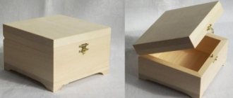
How to make a milling table cover
1. Cut out two blanks for the cover N with allowances of about 6 mm in length and width (Fig. 3). Mark the area on the bottom workpiece where the router mounting plate will be located. Glue both pieces together and fasten them additionally with clamps and screws, but avoiding glue and screws in the marked area. Leave the glue to dry overnight and then file to the specified dimensions.
2. Cut out the end edge trims O to match the width of the cover N, and glue them in place, aligning with the top and bottom sides and the front and back corners. Then cut out the longitudinal edge plates P, determining their length in place. Glue them to the lid, carefully aligning them. Finish sand the N/O/P cap with 180-grit sandpaper.
3.Cut a piece of melamine laminate that is 25mm larger than the length and width of the N/O/P cover. Glue it to the lid, aligning it in the center. Using a copying cutter, remove the protruding plastic overhangs flush with the edge trims O, R.
Manufacturing of bed and table top
The bed of a homemade milling installation must be highly stable and reliable, since it will bear the main loads. Structurally, it consists of a frame with supports on which the tabletop is fixed. As a material for the manufacture of the frame of the bed, you can use metal profiles connected by welding, chipboard, MDF, wood. It is advisable to first prepare drawings of such a device. They must indicate all structural elements and their dimensions, depending on the dimensions of the parts that are planned to be processed on such milling equipment.
Processing options with different types of cutters
The lower part of the bed from the front side must be deepened by 100–200 mm so that nothing interferes with the feet of the milling machine operator. If you are going to process linings for doors and the ends of facades for them on your homemade machine, then the dimensions of the frame can be as follows: 900x500x1500 (height, depth, width).
One of the significant characteristics of the bed for a homemade milling machine is its height, on which the ease of working on such equipment depends. According to ergonomic requirements, the most suitable height for equipment used while standing is 850–900 mm. It is advisable to make the lower parts of the frame supports adjustable. This will make it possible not only to compensate for uneven floors, but also, if necessary, to change the height of the milling table. To make a turntable with your own hands, just fix special wheels on its legs.
The assembly of approximately such a table is discussed in option No. 2
You can make a low-price, highly reliable milling table from the top of an old kitchen table. Such countertops are usually made of chipboard sheets 26 or 36 mm thick, coated with wear-resistant plastic. Their surface ensures good sliding of the workpiece, and the chipboard base perfectly dampens vibrations that occur during operation of the equipment. If you make a desktop for a machine with your own hands, then MDF and chipboard (LDSP) boards with a thickness of 16 mm or more are suitable for these purposes.
Purpose
The milling table is designed for mounting a router and other electrical equipment, moving it vertically and installing the tool at a given height. A comfortable workspace is created on the tabletop, stops, guides and other devices are installed. A vacuum cleaner hose is attached to the working surface. It pulls out shavings, improving the quality of processing and clearing the air of small sawdust.
The following is produced on milling tables:
- plane milling;
- trim;
- selection of grooves;
- cutting of thorns;
- figured processing of edges and planes.
Furniture parts, decorative fronts of cabinets and bedside tables, baseboards, shaped frames and other products in large quantities are made on tables with a router.
Important!
When working on a milling machine, the worker only has wooden parts in his hands that do not need to be fastened. This significantly improves equipment productivity and reduces labor intensity.
Milling table design
If you wish, you can make a homemade milling table from a regular workbench, but it is better to make a special design. This is explained by the fact that a machine with a milling cutter creates strong vibration during operation, so the bed used to fix the milling cutter must be highly stable and reliable. It should also be taken into account that the milling device itself is attached to the bottom of the tabletop for the milling table, so there must be enough free space under it.
When attaching the device to the top of a homemade table for a manual router, a mounting plate is used, which must have high strength and rigidity, or special clamps for a milling machine. Such a plate can be made of metal sheet, textolite or durable plywood. The bases of most router models already have threaded holes; these are what are needed to connect such a device to the tabletop and mounting plate. If there are no such holes, you can drill them yourself and cut threads into them, or use special clamps for a milling machine.
Milling cutters for various types of processing on a milling table
The clamps for the milling machine or the mounting plate must be located at the same level as the tabletop; for this purpose, the latter is sampled with the appropriate dimensions. It is necessary to drill several holes in the plate, some of which are necessary to connect it to the tabletop using self-tapping screws, and others so that such a plate can be fixed to the base of the router. The screws and self-tapping screws that you will use must have a countersunk head.
To make turning on your device more convenient, you can place a regular button on the tabletop, as well as a mushroom button, which will make your device safer in operation. To increase the convenience of your home machine, you can attach a long metal ruler to the surface of a milling table made for a manual router with your own hands.
Before you start constructing a milling coordinate table with your own hands, you need to determine the place where it will be located, and also decide what type of milling equipment you want to make. So, you can make an aggregate router with your own hands (the table will be located on the side of the sawing equipment, serving as its extension), a compact desktop machine, or free-standing stationary equipment.
You can opt for compact benchtop equipment for working with wood and other materials if you access it irregularly or often use it outside your workshop. This installation, which is distinguished by its small size, takes up very little space, and if desired, it can be hung on the wall.
If the size of your workshop allows, then it is better to adapt the base of a stationary milling machine for the milling machine, which is much more convenient to work on than on desktop equipment. To make such a device more mobile, it can be placed on wheels, with which you can easily change its location.
A simple milling table or table for a drilling machine can be made very quickly. To make such a structure, which can easily be placed on a regular desktop, you will need a sheet of chipboard on which the guide elements are fixed. As such a guide, which can be used as a parallel stop for a milling table, an ordinary board of small thickness, which is attached to the tabletop using bolted joints, is suitable. If necessary, you can attach a second such board in parallel, which will serve as a limiting stop.
To insert a router into a table, you will need to make a hole in a sheet of chipboard to accommodate it, and it will be fixed to the tabletop using two clamps. After this, the manufacture of the milling table can be considered complete. To make the use of this design more convenient, you can place simple clamps for a milling machine on the tabletop.
Do-it-yourself milling table: step-by-step instructions:
Milling is a wood processing process that requires high precision and quality. That is why special tables are used for such work.
Today there are a huge number of router tables on sale, but their prices are very high. That is why home craftsmen are increasingly trying to make a milling table with their own hands.
Let's talk about how to implement this idea and what to pay attention to.
About the table design
Often the milling table is installed on a workbench, however, it makes sense to create a separate structure. In this case, the product must be rigid and stable.
Some structural elements need to be upholstered with stainless steel to increase strength, and a metal profile should be used to add rigidity. The router itself is mounted at the bottom of the tabletop. During operation, no structural elements should interfere with it.
It is also worth noting that if you are planning to make a milling table with your own hands, then install the mounting plate. The router will be attached to it, so it must be very strong and stable.
It is advisable to use a material such as textolite or metal sheet. In general, assembly is quite simple, but not fast. Let's talk about everything in order.
Necessary tool for the job
Before you start designing something, you need to acquire a tool so that you don’t have to run back and forth during the process. An electric jigsaw will be very useful for you. If there is none, then you can get by with a regular hacksaw, although the labor intensity in this case will increase significantly.
The same applies to the plane. A regular one will do, but an electric one is better, since working with it is much easier and faster. A chisel is also a necessary attribute. A block with sandpaper can successfully replace a grinding machine. In addition, it is advisable to have a screwdriver and an electric drill in your arsenal.
After this, you can begin assembly work. I would like to draw your attention to the fact that if you want to obtain accurate products, then place a ruler on the table. Often, making a milling table with your own hands goes without any problems, but before you start, it is advisable to acquire the drawings, which you can find in this article.
Deciding on the type of table
The first step is to decide where to install the milling table. In addition, there are different types of such products. For example, there are portable milling tables that are distinguished by their ergonomics and small size.
In addition, there are stationary ones, they are assembled specifically for the router and are the most preferable option if you plan to perform large volumes of work. There are also aggregate milling tables. In this case, the router is installed as an extension of the saw table.
This saves space, but is not always convenient or practical.
If you don't plan to use your router table very often, then a portable option is for you. It does not take up much space and can be easily moved if necessary. If there is plenty of space in the workshop, then a stationary table is better. For ease of movement, equip it with wheels.
Making a milling table with your own hands: part 1
First of all, we take 2 clamps. After this we make the main hole for the cutter. As a guide, you can use thin plywood secured with bolts. After this we move on to the bed. This element is a stationary element of any milling table.
By and large, this is a frame on supports, in the upper part of which there is a tabletop. Almost any material can be used to make the frame, from plywood to steel sheet. The most important requirement is to achieve maximum rigidity and stability, so it makes sense to take care of reliable fasteners.
The size of the bed should be selected according to the maximum dimensions of the workpieces that you intend to process.
We continue work
The next step is to take care of the bottom of the bed. It must be deepened by 10-20 centimeters in relation to the overhang of the tabletop.
Often, a bed 150 centimeters wide is sufficient for processing large workpieces. For example, on such a bed you can work with door overlays, ends of facade blanks, etc.
The height of the bed in this case should be about 80-100 cm, and its depth should be about 50 cm.
It is extremely important to pay attention to the height of the bed. As noted above, the optimal height is 80-100 cm. But it is best to try making adjustable supports. In this case, you can adjust the height to suit you. The most common table material, such as chipboard, is suitable. For example, a tabletop from a regular kitchen table is suitable; the thickness can be from 26 to 36 mm. It is desirable that the coating be wear-resistant. But all this is not enough to make a milling table with your own hands. Drawings or at least a sketch are a mandatory attribute.
About the mounting plate
The router is attached not to the table, but to a special plate. As a material, it is best to use something durable, but at the same time thin. Let's say a steel sheet would not be the worst solution. This is quite durable, but not the most convenient option. If you value comfort, then give preference to PCB with a thickness of 4-8 mm.
In the center of the mounting plate, you need to drill a hole with a diameter that will be equal to the hole in the base of the router. The sole is equipped with threaded holes that are necessary for fastening. If there are no holes, you need to make them yourself. Of course, you can also use special clamps for clamping.
Any solution that provides a reliable and strong connection will do.
Assembly instructions
At the first stage, the tabletop is attached to the frame. A mounting plate is installed on the frame. Before attaching it, you need to attach it to the table and trace the outline with a pencil. Then a seat is selected.
As a priority, the corners of the seat should be slightly rounded. Next, using a cutter that is larger than the thickness of the plate, a through hole is made in the shape of the router sole. At this stage, accuracy is not too important.
Under the countertop, provide space for a dust collector and other accessories.
The milling cutter is started from below, after which it is attached to the plate. The mounting plate is attached to the frame using self-tapping screws. The caps must be recessed with self-tapping screws so that they do not interfere with the work process. In principle, we practically made the milling table with our own hands. It is advisable to equip a homemade table with upper and lower clamping devices.
Briefly about installing the drive
If you are assembling a full-fledged milling table, then you need to take care of the electric drive. In particular, you need to choose the right power.
The minimum should start at 500 watts, but this will only be sufficient for shallow sampling. The optimal solution would be a 100-watt electric motor.
Making a milling table + (Video)
A well-made router table significantly increases the efficiency of working with a hand router. However, buying them can cost a pretty penny, because it will be much easier to make such a table yourself, using special drawings for this. This will allow you to save a lot of money and, moreover, the process will not take too much time. There are several types of milling tables: stationary, adaptive and portable. In this article we will talk about the stationary option, because it is the most difficult to implement. This means that having learned how to make it, other types of milling cutters can be made without difficulty.
Selection of drawings and materials
Before starting any work, you should decide what kind of result you want to get. The easiest way would be to make a milling table based on a regular workbench, but it is better to make a separate structure. But if you still take an ordinary table for this purpose, then it must be very strong and stable
It is also important to choose the right dimensions: for example, the optimal height is approximately 90-100 cm. An even better solution would be a table with adjustable height, because this will allow the milling machine to be adjusted to the needs of the master
A general view of the milling table elements can be seen below.
As for materials, there are also subtleties here. Often the covers for such a table are made from MDF board. In general, this is justified: they are inexpensive, lightweight and easy to use. Phenolic plastic is also a popular material - it is stronger and more durable than MDF. But also more expensive - by about 20%. You can make a tabletop from a sheet of metal
One thing is important - the surface must be absolutely smooth, since the workpieces must move easily across the table surface without clinging or getting stuck anywhere. The thickness of the cover should not exceed 35 mm
Tools for work you will need:
- Electric drill.
- Chisel.
- Sander. In principle, sanding can be done manually using sandpaper, but it will take much more time.
- Plane.
- Screwdriver.
- Jigsaw.
As you can see, both materials and tools for making a milling table are not so difficult to get
But it is extremely important that everything is of high quality, because the durability and reliability of the product directly depends on this.
Table manufacturing stages
When all the preparatory work is completed, you can proceed directly to the manufacture of the product. Everything is done in several stages. They will be listed below.
Assembly of the frame. This is the name of the table on which the remaining parts of the milling machine will be mounted. If a ready-made table is taken as a basis, then this point can be omitted. However, as already mentioned, it will be more convenient if the bed is made from scratch. For example, the following option can be considered quite successful: Installing a mounting plate. It is necessary to install a not too thick board or textolite on the table cover. The thickness of this part should not exceed 8 mm. Again, you can take a metal plate for this purpose - such a part will last a long time. A hole is made in it, the size corresponding to the router. 4 holes are also made along the edges, with the help of which the mounting plate is attached to the table top
It is important that the plate does not protrude beyond the edges of the tabletop, otherwise they will constantly cling to it. You can see what this device looks like in the picture below.
Making a longitudinal stop
It is necessary for performing many milling jobs. The plate used as a guide must be perfectly flat and strictly perpendicular to the tabletop. A guide with a T-shaped slot will be convenient to use. The parallel stop is attached to the frame using a certain type of clamp. To ensure that the plate remains perpendicular to the tabletop, special support legs are used. This is what the guide bar looks like:
Installing a groove for a movable stop. Usually, longitudinal edges are processed using a router, but sometimes you need to work with grooves located across the boards. It is for such cases that the rip fence is designed.
There are some nuances associated with the implementation of each of the points. However, anyone who has experience working with wood products will be able to make a milling table
It is only important to pay close attention to the task at hand.
Main varieties
Each master chooses a table that is convenient for himself or makes it with his own hands, increasing the number of models. Based on the design of the base and shape, all tables for routers are divided into several groups.
Bench
The model is a base with legs. The space under the tabletop is open. All mechanisms, including the elevator, are attached to the lid. Made from various materials:
- profile pipe;
- metal corners;
- tree;
- plywood;
- MDF and chipboard.
The advantages of the design are its low weight and ease of manufacture. To increase rigidity, it is necessary to make spacers and gussets.
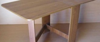
Portable table top
Design with small legs. Installs anywhere on a workbench or table. The base is made of wood or profile pipe. The equipment usually only has a guide ruler. The table is easily portable, installed anywhere and put away on a shelf when not needed. Suitable for periodic work on equipment. The structural rigidity is low.
Separate
Stationary milling table with solid base. In the space under the tabletop, closed shelves and drawers are made for storing interchangeable tools, accessories and other things necessary for work. The design is durable, made of wood or profile pipe. Sheathed on all sides with plywood and boards.
Professionals working at a separate milling table have a large selection of different tools and perform various operations. The cost of equipping a workplace is offset by ease of use and increased productivity.
The process of making a homemade table
Cut a plate from plexiglass for the platform measuring 50x40 mm. Using a cutting knife, cut two lines lengthwise and crosswise down the center of the sheet.
After this, the tape is removed. Using a simple felt-tip pen, draw the line of the slot so that it appears clearly.
Two strips measuring 500x50 mm are cut from plexiglass to make guides for the milling table. The edges of the guides are ground to reduce friction.
Next, in the lower side of the plate for the platform, 3 holes are drilled on both sides. This operation is performed with a drill with a chamfer head. Countersunk head screws will be inserted into these holes from below. 3 holes are cut accordingly on one of the plexiglass guide strips. Then connect one guide to the platform and attach nuts and washers.
A conical cutter is installed on a hand router. The router is pressed against the platform, the end of the cutter is aligned with the line in the center of the platform, and the bolt is clamped on the guide. Repeat this operation at the other end of the guide and tighten all the bolts. Screw the second guide in the same way.
Thus, the manual router slides along the plexiglass platform along the guides, which rigidly fix it on both sides, preventing errors and mistakes.
Then, using a milling machine, a groove for the cutter is cut, having previously marked its dimensions on the platform with a felt-tip pen. Since its width should be 1 mm larger than the largest available finger cutter, the groove is made in 3 passes.
The grooves for fixing the table are marked and cut in the same way.
At the next stage, it is necessary to make equipment from polystyrene for attaching the limiters. The limiters move and are fixed on the limiter base, which is mounted on the table platform.
Sequence of operations:
- Cut polystyrene blanks on a circular saw.
- The grooves are milled.
- Drill holes for fastening.
The workpiece is cut into 2 symmetrical parts. Insert a screw into the base for the stop and glue it to the table platform.
Grooves are milled into the blanks of the stops and inserted into the bases by threading the screws into the holes of the grooves. If necessary, protruding screws are cut off with a grinder and the burrs are smoothed with a file.
The following operations are carried out in 3 steps:
- Drill holes in the clamping bars.
- The cutter is used to select a countersunk for the heads of furniture bolts.
- Insert bolts into holes.
On the back side of the platform, bars are inserted so that the bolts fit into the grooves for fixing the table. Wings are screwed onto furniture bolts and limiter screws.
The design of the milling table is made by hand and is ready for use.
Option 4. Milling machine based on a desk
A milling machine based on a desk is considered an economical and convenient solution. The list of photo drawings contains a table with specifications of parts by size and recommended material.
Part sizes and materials
Next we will talk about other features of milling tables.
How to make a mounting plate
Due to the thickness of the table cover, in order to maximize the output of the cutting tool, it is necessary to take a smaller thickness of the mounting plate. It follows from this that, with a small thickness, it should have sufficient strength.
The plate can be metal or textolite. These materials best meet the requirements of strength and rigidity. The optimal plate thickness should be 6 mm. It is made in a rectangular shape, a hole is drilled in the middle of the part with a diameter corresponding to the hole on the base of the router. To increase the range of use of the tool, rings of different diameters are used. There are holes in the plate for connecting to the router and attaching it to the tabletop.
The holes in the plate must match the location and size of the holes on the base of the router. To accurately mark the plate, you need to draw a sketch with dimensions or secure it on the table using clamps.
The nuances of assembling a milling table with your own hands
When assembling the milling device, secure a metal ruler at the ends of the width of the table top; this will make it possible to set the parallel fence to the correct size and strictly parallel.
On the back side of the table cover, make holes for subsequent installation of the dust collector casing and additional equipment. The drawings and photos provided will help you correctly manufacture all components.
To make it easier to turn on and safely turn off your DIY milling machine, install a mushroom-shaped start button and a stop button on the tabletop.
Main parts of the milling table
We mean the set of elements from which it is not difficult to assemble the installation on your own:
- Aluminum guides.
- Steel plate for working area. It's also a mounting plate. A router is attached to it.
- Sheet of plywood.
- For the base there is an MDF panel.
On this kind of tables, it is advisable to install the buttons necessary for turning on and quickly stopping (emergency lights). Upper clamping devices are included in the assembly plan in case of working with large parts.
Table type
There are only three of them. Milling tables are:
- Aggregate. It is possible to expand the saw plane.
- Portable. Small size, easy to carry weight.
- Stationary. The structure is weighty and very difficult to move on your own.
Cover material
- The base, cover or working surface must be covered with plastic (if we are talking about an MDF panel). But such a table can become saturated with moisture, which will affect the quality of the milling cut, plus the grooves in the swollen panel lose their normal mobility.
- Phenolic plastic. Optimal for a machine, but more expensive than an MDF panel.
- Steel. Aluminum, stainless steel or rolled sheet. Sometimes they also install cast iron. But the issue of corrosion is solved with paint.
Groove for stop
This is just a recess for a movable longitudinal stop or a built-in carriage. The groove is an ideal element of the table design; additional devices are used due to it. An analogue of a groove is a movable slide. They are perpendicular to the longitudinal stop, plus they are also movable.
Fixing the router
The hand tool is mounted on a rigid plate made of steel, stainless steel, aluminum, textolite, etc. The plate itself is mounted with a recess so that it can be recessed into a level with the lid.
Longitudinal stop
Fixed on the table. Its purpose is to correctly feed the workpiece. Longitudinal stops are stationary. This is convenient for processing the same type of material.
Sliding stops are ideal for milling various elements according to dimensions. The quality of operation of the entire machine depends on the longitudinal stop, its stability and smoothness.
Manufacturing stages
Before assembling the structure, you should prepare all its components and check their compliance with the dimensions indicated in the drawing. Step-by-step manufacturing instructions:
- making a frame, coating wooden parts with paint and varnish, priming metal parts before painting;
- securing the working surface to the bed;
- making a recess in the frame for installing a metal plate with a slot for a cutter, onto which the tool itself will be attached from below;
- insertion of guides for mounting the stop.
Note! All connections must have a countersunk head and not rise above the work surface.
For safety reasons, the on and off buttons are installed on the side surface of the frame.
Marking the tabletop for the profile, mounting plate, grooves
DIY machine assembly option
An aluminum T-shaped profile is installed on both side ends of the table for fastening and free movement of a parallel stop in the form of a bar. The side strip is equipped with aluminum fasteners that fit into the grooves of the side profiles.
A rectangular cutout is made in the plank for the exit of the cutter. A guide profile is attached to the part, along which the vertical and angular clamps move. Clamps fix the passage of the wooden workpiece through the milling zone.
A parallel groove is cut in the tabletop to move the miter gauge slide. On one of the supports under the tabletop there are switches with an emergency stop button for the router.
The work platform is often made of MDF and construction plywood. The surface of such material wears out quickly. A more reliable tabletop is made of textolite. The textolite surface has high wear resistance and a low coefficient of friction.
The ideal option for a tabletop would be a steel sheet or an aluminum alloy plane. Since the platform must have technological grooves and holes, making such a part with your own hands will be quite difficult, and sometimes impossible. A solution can be found in using parts of old equipment.
Router plate
An opening is cut out in the center of the tabletop to install the work plate. It is better to make the plate from the same PCB. A round hole is made in the slab. Round inserts are made under the hole. By combining inserts, select the through hole in diameter for the desired cutter.
The ring inserts, like the plate itself, must be flush with the entire surface of the work table. The rings ensure that the cutter fits tightly into the working area.
Fraser
The power plant functions like an ordinary drill. The milling chuck clamps the cutter axis and imparts rotational movement to it. The unit is attached from below to the working plate. When designing a table, it is necessary to take into account the preservation of space for placing the device under the tabletop.
A compact electric motor is used as a milling cutter. An experienced craftsman can make a homemade power tool. In some cases, an electric drill is used. To get rid of this problem, purchase a ready-made manual router. The retail chain offers customers a wide range of hand-held power tools of this type.
Manual milling machines from different manufacturers have approximately the same set of options and overall dimensions. The tool is mainly intended for processing wooden workpieces.
A milling machine allows a worker to control the processing process with two hands, and when working with hand tools, the hands are busy holding the unit itself. It is advantageous to place a manual milling cutter in a homemade machine design.
Mounting plate
The polymer sole of the router is removed and a mounting plate is cut along its contour. The mounting plate is made of metal sheet, no more than 6 mm thick. Mounting holes are drilled in the working area along the screws securing the router through the mounting plate.
The holes are made from the side of the working surface with a countersunk so that the screw heads do not protrude above the plane of the table.
Elevator
An elevator is a device for moving something vertically. In this case, this concerns the milling unit. The manual router is equipped with a lift. The problem of installing an elevator becomes relevant when home-made devices are used as a power plant.
You can purchase a ready-made factory-made elevator. There are many options for making homemade lifting devices published on the Internet. The main task of the lift is to accurately fix the cutter vertically. The protrusion of the conical cutting surface of the cutter determines the depth and width of the wood sample in the workpiece.
One of the most popular options for a homemade elevator is to move the router on a vertical threaded metal rod.
Diagram of a homemade router lift
A shelf is installed under the table into which a rod with a flange nut is inserted. A flywheel is installed higher on the rod. By rotating it, you achieve the desired height of the cutter above the surface of the work table.
Rotary milling table
The rotary model of the machine is a complex structure that ensures the tilt of the wooden workpiece in relation to the cutter. Thanks to this feature of the machine, wooden blanks of complex shapes are produced. It is almost impossible to assemble such tables at home.
Step-by-step manufacturing instructions
To make milling tables, you can use old furniture and workbenches or make the entire structure yourself.
Manual workbench with plate
The simplest device for working with a router. The workbench has durable legs and a frame on which a tabletop with a milling plate is placed. Making your own is simple.
- Cut a hole in the workbench with a protrusion around the perimeter, the size of the milling plate.
- Attach the router to the plate and fix it in the tabletop.
- Mill the ends and make guides out of them for moving the stop ruler.
- Cut a ruler out of plywood. Attach strips to its ends, hanging down and sliding along the ends.
- Cut a hole in the center of the ruler and install the pipe under the vacuum cleaner.
The machine is ready for the production of simple parts, milling of side surfaces, and figured trimming.
Based on written wood
A milling plate is outlined in the table top. A round hole is cut in the center into which the router body fits. The remaining surface of the rectangle is milled and understated. Places for adjusting and fastening screws are marked along the plate, and holes with a diameter of 2 mm are made.
The guide ruler is cut out. Brackets are installed on it, sliding along the side ends. Additional stops are made at the back. In the center there is a hole for the vacuum cleaner pipe. A T-shaped guide for a transverse ruler is attached to the front end. The router, mounted on a milling plate, is installed through a hole in the tabletop - lowered down. For the elevator, a support board is placed between the pedestals.
Homemade from plywood
To make the table itself, multi-layer plywood 16 mm thick is suitable. It is better to make the tabletop thicker, 22 mm. The lower part consists of legs and a lid with a hole in the center. Plywood gussets are placed on the corners of the milling tabletop. Their internal dimensions should be 2 mm larger than the perimeter of the base. The table top fits onto a frame with legs and is secured with 8 screws around the perimeter.
Portable
A small low table made of plywood has:
- 2 side planes-legs;
- a longitudinal strip between them for rigidity;
- a small tabletop with a plate for fastening;
- thrust bar.
The height of the table is determined by the parameters: it is convenient to work when it stands on a workbench and a router is placed underneath. The advantages of the model are its compactness and low weight. The portable milling table can be removed from the workbench at any time and placed on a shelf, freeing up space for other work.
Functional
A table on which you can make curved edges, mill baseboards and planks, and work with templates. It consists:
- base made of profiled pipe;
- table top;
- parallel stop;
- perpendicular stop;
- pressing combs;
- replaceable rings.
You can additionally install a vice and other devices on the table. Drawers are built into the base, shelves and doors are made to close them. In the center of the parallel stop on the reverse side there is a pipe for connecting a vacuum cleaner.
The tabletop is made of thick textolite 20 mm thick. A milling plate with adjusting screws is installed in the middle. In front, an aluminum tire with T-shaped slots of different widths runs along the entire length. A perpendicular stop and pressure combs move along it.
For hand router and jigsaw
On a combination table you can mill on one side. The other is designed for sawing boards and plywood. The table frame is made from corners or profile pipes. It must withstand heavy loads and dampen vibration. A hole is made on one side of the tabletop for the router tool exit and a plate is attached. A rectangular plate with a slot for a disk cutter is installed on the other, and a jigsaw or lamellar router is mounted underneath. Guides are mounted on the side of the frame. A stop ruler moves along them. It is used when both devices operate.
For mini CNC router
The table for a mini CNC router is structurally different from its counterparts. The unit is located on top and works independently, according to the program. There is no need to make an elevator for it. The table is made of silumin. T-shaped grooves are cut on the working surface to secure the part. Guides are attached to the sides of the bed, along which the milling cutter moves longitudinally, which is controlled by an electric drive through the shaft.
There is a portal between the posts for the transverse movement of the tool. In the vertical direction, the cutter moves along with the spindle when the cross screw rotates. It is better to buy ready-made guides or make them from wood, but they will quickly wear out. Cut the side posts out of plywood, attach a round guide and a lead screw to them.
Wall
The wall-mounted table is ideal for workshops with a small area. When folded, it looks like a hanging cabinet. In working condition, the lid turns into a work table for the router. Tools are stored on shelves inside the wall part.
- Make a wall cabinet with a hinged door from boards or thick plywood. A smooth pin is used for rotation. Near the side end, a latch is installed on the outside to hold the door in a horizontal position.
- Make holes in the lid and secure it on top - the inner side, the table top of the milling machine with a stop, a plate for attaching the router and other devices.
- Make a hole in the side of the cabinet for the vacuum cleaner hose.
The disadvantage of a wall-mounted table is the need to remove the router every time. When work ends. When you close the countertop door, it sticks out along with the wires.
Mini table
The compact model takes up little work space, approximately 1 square meter. The base and legs are welded from corners and covered on all sides with thin sheet steel. There is a door on the side for access to the router. On the front wall there are start buttons and handwheels for the elevator and router. A small tabletop with a ruler located on top ensures comfortable work.
Reference! A compact table is the most popular option for installing a router. For mobility, wheels are attached to the legs.
For milling machine
The table is made of both aluminum and its alloys. Ready-made guides and rulers are used.
- The base is cut out from the plate.
- Longitudinal guides and a screw between them in the center are attached to it.
- A sled made of the same sheet is placed on top. At the bottom there is a nut mounted on a screw.
- A similar design, only in the transverse direction, is mounted on a skid.
- The table is installed on top. A transverse screw is passed through it.
For mechanical movement, drives are installed on the free ends of the screws. The coordinate table is used with a milling head stably mounted on the frame, and is installed as an additional device on the machine.
Coordinate
A manual coordinate table is made from chipboard, cylindrical wooden posts with pulleys and small pieces of beams. From the finished parts you will need 6 round guides with a diameter of 10 mm.
- Cut a base from thick plywood. Attach 2 strips to it from below at a distance of 10 mm from the side ends instead of legs.
- Make 10 wooden cylinders with a height of 60 and 80 mm (5 of each type). Drill through holes with a diameter of 8 mm in them.
- In the corners, closer to the edge of the table, drill holes and install 2 cylinders of different heights. Each standard size should form a rectangle. Install a pulley on top of them.
- Bolt the pulleys with their stands to the base.
- Place the remaining cylindrical workpieces on the right and left on the front of the machine. Attach handles to the pulleys on top and bolt them together so that they rotate together.
- Make pillows for the guides from wooden cubes.
- Before installing the transverse and longitudinal guides, place cushions on them with a blind hole for the ends of the shafts.
The result should be a rectangle of external guides and shafts with a carriage for the router arranged crosswise inside. To complete the work, pull 2 thin cords, each around the perimeter and handle of the same height. Fix one of them on the movable cushion for longitudinal movement, and attach the second to the lateral movement. Pull the cord around the perimeter through the pulleys. When the handles rotate, the cord will move the router in the longitudinal or transverse direction. The cutter will select the material by moving along the coordinates.
Milling table assembly
A universal milling table or begin to assemble by attaching the table top to the finished frame. The mounting plate is applied to the place on the tabletop where it should be placed according to the drawing, and its outline is traced with a pencil. This is necessary in order to select a recess for the plate along the marked contour, for which a manual milling cutter with a tool with a diameter of 6–10 mm is used. The size of this recess should be such that the plate fits into it at the same level as the surface of the tabletop.
It will not be possible to make a recess with right angles using a round cutter, so the corners on the plate itself must also be rounded using a file. After fixing it in the tabletop, it is necessary to make a hole in the mounting plate with dimensions corresponding to the diameter of the router base. It is done using a straight cutter, the thickness of which should be greater than that of the tabletop itself.
PROMA, priced at about 6 thousand rubles, is one of the cheapest factory milling tables
To perform such an operation you do not need a drawing, since it does not require high precision. On the back side of the tabletop, it is also necessary to select a certain amount of material, since the dust collector casing and other devices will need to be placed at the bottom of the table. To quickly perform all the operations described above, you can rely on the drawings or photos posted in this article.
The final stage of assembling a homemade milling table is connecting all its structural elements. First, a router is started from the bottom of the tabletop, its base is screwed to the mounting plate. Then the plate itself is attached to the upper surface of the tabletop using self-tapping screws with countersunk heads, which must be completely recessed into the prepared holes. Only after performing these operations is the tabletop itself securely fixed to the frame.
How to make a mounting plate
The mounting plate must be wider than the diameter of the cutter if you plan to work with several cutting attachments. It is more profitable or cheaper to form this element from 20 mm birch plywood.
But it is more practical to work on a homemade machine with cast polycarbonate as a mounting plate. The essence of the work is this:
- Remove the soleplate from the power tool, having first placed the mounting plate face up.
- Temporarily connect the plate and sole using double-sided tape.
- Select drills to match the diameter of the factory fasteners and drill the correct holes for fastening on the plate.
- Next, connect the homemade plate with the router and place it on the table for adjustment.
- An 8 mm drill is placed in the collet and the motor is lowered. You need to touch the plate with the drill and mark the center.
- Next, follow the mark to make a hole of the required diameter.