Metal planing is the process of removing the surface layer of the surface being processed in order to give it the required shape and size.
A metal planing machine is a metal-cutting machine designed for processing flat parts or shaped surfaces. The movements performed by the machine can be reciprocating and rectilinear. They will depend on the surface area being processed and on the technical characteristics of the machine.
The technology for manufacturing a part includes several stages. One of them is to process the product on a metal planing machine. There are several types of machines designed to work with metal at different stages of production of parts, giving them the required shape and size.
Scope of application and purpose
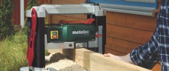
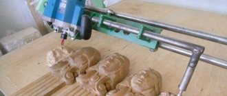
homemade machine
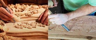
Industrial and home-made planing equipment is used for one-sided processing of flat surfaces of wood products. The main area of application of the machines is furniture and woodworking production. Perpendicular surfaces are planed on them, chamfers are selected at the desired angle from the sidewalls. Precision processing is important when assembling furniture; jointing equipment allows you to obtain a part of a given size. Planing mechanisms are often used at home in domestic workshops.
A jointing machine does not allow you to plan thickness to size, or make parts with parallel surfaces!
Construction of wood and metal working planing machines
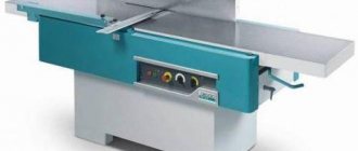
Planing machine is equipment used for processing flat, shaped and ruled surfaces by chiselling, also called slotting machines.
Such units are used to form grooves, grooves and stamps on metal and wooden parts in individual and small-scale production. This article examines planing machines, we will study their design features, operating principles and varieties, and also learn how to make a simple planing machine with your own hands.
Classification of jointing machines
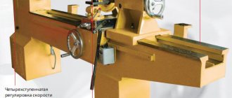
Depending on the number of planing devices, planing machines can be double-sided or single-sided. All planing devices are divided into categories according to the width of the planing surface, the length of the work table and the rotation speed of the knife shaft.
According to the processed width of the workpiece, mechanisms are distinguished:
- by 40 cm;
- by 50 - 52 cm;
- at 60 - 63 cm.
Compact homemade units for the home have a smaller processing width.
According to the length of the working surface, two groups of devices are distinguished:
- with a length of less than 250 cm;
- with a length from 250 to 300 cm.
Larger workpieces can be processed on long tables. The quality of jointing also improves.
According to the frequency of torsion of the working shaft, machines are divided into two categories:
- 4700 - 4800 rpm;
- 5000 rpm.
Industrial motors can operate at speeds up to 12,000 rpm.
Machine assembly sequence
For the work to be successful, first working drawings and a brief description of the device are drawn up.
- The assembly of the machine begins by transferring the dimensions from the drawing onto the workpieces, and full-size parts are manufactured. In this case, you need to pay attention to the location of the rotor bearings.
- A rotor with a bearing is installed, the belts are attached to the knife shaft and the engine.
- The serving and receiving tables are installed. The moving parts of the machine are covered with sheets of metal or plywood.
- The starting switch/switch is installed.
- A test start-up of the unit is performed.
Video: jointer instead of thickness planer.
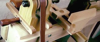
The device of a jointing machine
bed with attached blade shaft
The design consists of the main elements:
- working surface;
- bed;
- guide;
- knife shaft;
- circular fence.
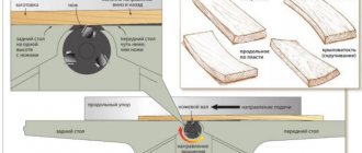
The working surface of the planer consists of two plates: back and front. The level of the back plate coincides with the level of the top point of the cutter blades. The front level is set lower to the extent that the material is removed during processing. Typically the level difference is no more than 1.5 millimeters. This is enough to qualitatively process the surface of the part in two steps.
The plates are made of cast iron, and to make the table more stable, stiffening ribs are provided. The edges of the slabs are covered with steel plates that protect them from destruction. They are also chip breakers.
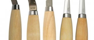
The knife shaft is located between two plates; cutters are attached to the shaft. For high-quality processing, it is necessary to select the same cutters. As a rule, single-edged knives are used that can be sharpened. Double-edged cutters, when severely dull, are thrown away and replaced with new ones; they cannot be sharpened. As a rule, machines for household workshops are equipped with cutters made of tool high-speed steel. To work with dense types of wood or pressed boards, carbide-tipped cutters are used.
The guide is fixed with bolts in the provided holes. The ruler can move in the transverse direction depending on the size of the part.
A circular fence is installed on the front of the slab; it fits tightly to the guide due to the spring. The fence covers the knife shaft. The movement from the motor to the blade shaft is transmitted through a belt drive.
The optimal size of wooden parts for processing on a jointer is from 100 to 150 cm. Too long parts hang down and create inconvenience when working at home, while short ones are dangerous.
How to joint boards correctly
Jointing is the process of processing wooden products using a jointing machine. Initially, the workpiece is fixed on the work table. During the jointing process the following rules must be observed:
- The jointer must be held with two hands: the left one should be located on the control handle, the right one should be on the block.
- During the planing process, the device must be guided along the grain of the wood. It is recommended to push the device forward under the pressure of its own weight.
- To process the edge, you need to turn the block with the desired side towards the blades and plan it according to an identical algorithm.
During the jointing process, the surfaces of the boards (faces) become parallel across the entire width. When working with a jointing machine, you must follow safety precautions:
- When the machine is turned on, do not touch the blades with your hands.
- You need to wear special clothing when working with the tool. The head must be protected with a hat, hands with gloves, eyes with goggles, and feet with specialized shoes. It is important that the overalls fit snugly to the body.
- During the jointing process, it is necessary to use clamping holders to protect the operator's fingers from the knives.
To avoid cutting off excess wood, it is recommended to mark the surface of the block with a chalk line. If it has completely disappeared, then the surface of the workpiece has become smooth.
Setting and selecting mode
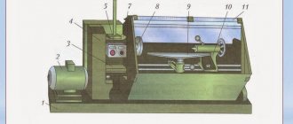
mechanism for changing the distance between the knife shaft and the edge of the table
Before starting work, you need to calculate the thickness of the material being planed and the speed of movement of the workpiece (for equipment with an automatic feeder). The size of the layer depends on the initial state of the tree and is determined experimentally. To do this, several (no more than five) workpieces are processed. If untreated areas remain on the surface, the slab is lowered slightly. If the workpiece is warped by more than 2.5 mm, processing is carried out in two stages.
When the height of the slabs is set, measure the gap between the edge of the cutters and the jaws of the slabs, which should be from 2 to 3 millimeters. To determine the gap, a calibrated plate is used, which should be inserted into the gap easily, but without gaps. If the gap exceeds 3 mm, the part becomes covered with tears; if the gap is less than 2 mm, the cutter is destroyed.
In addition to setting the slabs in height, it is also necessary to determine the location of the guide. When processing wooden blocks, the gap between the ruler and the left edge of the knife shaft should be slightly larger than the width of the block. Gradually, the knives become dull and the guide moves to the right, involving other parts of the cutters in the work. The ruler moves across the tabletop on a rack and pinion device driven by a flywheel. To make a corner chamfer on an edge, the guide is installed using a template or square and secured with a screw.
Automatic feeders regulate the feeding of parts without stoppers, with low pressure. When processing edges, they are placed parallel to the ruler.
The correct settings of planing equipment are determined experimentally. Allowed errors are:
- on the plane no more than 0.15 millimeters per meter;
- perpendicularly - no more than 0.1 millimeter per 10 cm.
A type of metal planing machines.
Metal planing machines are a group of equipment. It includes the following machines:
- slotting,
- lingering,
- longitudinal planing,
- cross-planing,
- shaped-planing.
The division of machines into transverse planing and longitudinal planing depends on the movement of the part itself or the cutting tool. In longitudinal planing machines, the main movements are performed by the workpiece, which is fixed in a special way. They are designed for working with small workpieces. The cutters in it move at a certain speed.
Cross-planing equipment for metal involves working with medium-sized workpieces. Their function is also to make holes, recesses and channels.
.
:
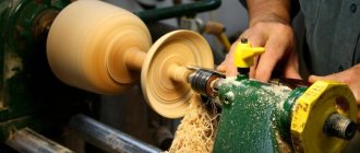
Working principle of a jointer
chipboard guide ruler
One person is enough to operate single-sided jointing equipment at home. He examines the condition of the workpiece and places it with its convex plane up on the front plate. With both hands he presses it against the ruler and points it at the cutters. Next, the already trimmed side is pressed with the left hand to the surface of the back plate. The master inspects the processed workpiece: if it is not planed enough, he sends it to the knives. It is advisable to avoid processing very warped workpieces, since too thick a layer of chips is removed. The remaining workpiece may turn out unacceptably thin.
When processing two perpendicular planes, the larger area is used first. Then it is applied to the guide and the second one is planed. The double-sided machine allows you to process both sides simultaneously.
- If “burns” or “mossiness” appear on the surface during processing, it’s time to sharpen the cutters;
- When working with parts shorter than 40 cm and narrower than 3 cm, they are held only with special pushers, and parts of complex shapes are held with templates;
- If the planed plane is curved or has the shape of an impeller, you should check the level of the tabletop plates and the blade shaft.
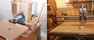
How to assemble a woodworking device at home?
In our country, there are still plenty of left-handers and kulibins, and many men can assemble a tabletop jointer, planer-thicknesser or circular unit.
This is all the more realistic because nowadays you can buy any rolled metal, electric motor, cutting shaft and any part for the machine. Moreover, in a special store they will cut the required part to the required size, drill it, and select fasteners. The craftsman only needs to draw up a detailed drawing of the desired unit, having decided on its purpose. A homemade jointing machine can be:
- Single-sided, perform only one working function of planing, process one face of the workpiece in one pass.
- Double-sided, processing the surface and edge of the workpiece in one pass.
- A jointer combined with a circular saw, that is, a shaft with blades and a circular saw “sit” on one shaft, while the efficiency of a woodworking unit assembled by yourself doubles.
- It’s difficult to do, but there are still craftsmen who add devices for drilling, sharpening, and grinding to the jointing unit.
Craftsmen most often combine a homemade jointing machine with a circular saw. This version has three work tables - two for feeding and receiving workpieces during jointing, and one for working with a circular saw.
Such combined structures have provisions for operator safety. When working with a jointer, the saw is covered with a special casing and vice versa, when the saw is working, the cutting shaft is covered with an adapted bar.
DIY jointing machine
homemade machine - side view
The frame of a small tabletop machine for home can be made from a rectangular metal pipe. A more powerful homemade design will be obtained from a 40 mm corner. The width of the bed depends on the size of the knives and the planned planing width.
At one end, two guides are welded to the frame, the upper edges of which coincide with the surface of the frame. In the middle of the frame, a knife shaft mounted on a pair of ball bearings is attached to bolts screwed into pre-prepared holes.
The working surfaces for the desktop machine for the home are made of thick plywood laid on bars. And to regulate their level, homemade overhead bolted connections are provided. Four connections for each plate: a pair at the front and a pair at the rear. A vertical block with a hole is attached to each part of the tabletop from below. A long threaded pin is threaded through the block and the upper horizontal of the bed, with the help of which the position of the table top relative to the knife shaft is changed.
There is another option for homemade fastening of the work surface: there are grooves made in the frame (4 pcs.), in the movable tabletop there is the same number of holes into which threaded pin heads are inserted. By tightening the nuts and moving the pins in the grooves, they change the distance between the blade shaft and the edge of the tabletop.
The back plate is installed motionless and adjusted in height to the knife shaft. A board or chipboard of a suitable size can serve as a guide ruler.
When choosing a motor, you should proceed from the nature of use of the future machine. For household needs, a power of 750 W is sufficient, but a motor with a power of at least 1.5 kilowatts can cope with more serious tasks.
A few more options for homemade jointers:
Review of factory models
| Model | W0108 | W0106FL | W0103FL | W0100 |
| Engine | 0.75 kW 220V | 0.75 kW 220 V | 2.2 kW, 220V | 3.7 kW 380V |
| Cutting width | 153 mm | 153 mm | 203 mm | 400 mm |
| Maximum cutting depth | 3 mm | 3.2 mm | 3.2 mm | 3 mm |
| Number of knives of the cutting shaft | 3 | 3 | 4 | 4 |
| Cutting shaft diameter | 61 mm | 61 mm | 78 mm | 98 mm |
| Table length | 1210 mm | 1535 mm | 1800 mm | 2250 mm |
| Feed table length | 700 mm | 760 mm | 880 mm | 1090 mm |
| Reception table length | 590 mm | 755 mm | 880 mm | 1090 mm |
| Table width | 255 mm | 255 mm | 330 mm | 420 mm |
| Table height from floor | 820 mm | 850 mm | 795 mm | 820 mm |
| Stop dimensions | 740 x 98 mm | 889 x 124 mm | 889 x 124 mm | 1195 x 150 mm |
| Packaged sizes | 1245x515x275 mm | 1600x360x250 mm | 1850x450x300 mm | 2300x820x1025 mm |
| Gross weight | 104 kg | 135 kg | 208 kg | 570 kg |
| Price | 52000 rub. | RUB 68,000 | 112000 rub. | RUB 229,000 |
W0108
W0106FL
W0103FL
W0100