SHARE ON SOCIAL NETWORKS
FacebookTwitterOkGoogle+PinterestVk
A wood lathe is a device that is used to process wooden products. In its structure it is similar to devices that are used for metal processing, however, there are functional differences. To select a suitable mini-machine for your home workshop, you need to study their structure, main technical characteristics, as well as the model range.
For processing wooden workpieces at home, desktop models of machines with low power are suitable
Material and components
All main working parts of the turning mechanism must be made of reliable materials.
The main rotating element of the engine from the washing machine can be used as a drive. Some craftsmen use motors from machines to sharpen knives, but finding a working motor from a washing machine is much easier. To operate the mechanism, you will also need a set of drive belts. For the tailstock, you need to find or make your own screw with the ability to fix it horizontally. One of the elements of the front clamp of a wooden workpiece can be a rotary chuck (head) from an old hammer drill or drill.
To avoid movement of the structure during operation, the base is made of a thick metal profile.
It is impossible to make a woodworking lathe with your own hands without using tools. To complete all the work you will need:
- drilling machine;
- files and sandpaper;
- Angle grinder (grinder) and a set of discs for cutting metal;
- welding machine.
You should also prepare screws, bolts and nuts for fastening the elements.
Tailstock
Making a tailstock is much easier. It consists of four parts:
- The base is made from angle steel, 100mm high, using the same principle as for the headstock. Two 50 mm corners are bolted across the top; in their shelves in the center there are cutouts with squares 40 mm wide.
- The guide (external) thick-walled square tube is 40 mm wide, 150 mm long and has an internal clearance of 20x20 mm. In the rear part you need to install a plug 6–8 mm thick and with a hole in the center of 8 mm; it is secured with two screws through the walls of the tube.
- The inner tube, also known as the quill, is made from a 20 mm profile tube, preferably thick-walled and milled exactly to fit the guide clearance. An M14 nut is welded in the rear part of the quill; a metal rod, widened to 5 mm, is inserted and welded into the front part, widened to 5 mm to fit a double-row bearing.
- The drive screw has a thread for a nut in the quill (it is advisable to make it trapezoidal); in the rear part there is a transition to an 8 mm thread for attaching the flywheel.
The principle of operation and the assembly diagram of the quill are quite obvious, but special attention must be paid to the alignment of the axes. The guide tube, fixed by welding in the cutouts of the corners, can rise higher or lower due to linings made of transformer steel. The headstock and tailstock must be absolutely aligned, the tolerance is only a couple of tenths.
As for the method of attachment to the frame, it is the same for both the headstocks and the tool rest. M14 or M16 studs are welded to the bottom of the headstocks, and a large plowshare bolt is inserted into the slot of the tool rest. The modules are tightened from below with nuts with rods welded to them like levers. For uniform, tight pressing from below, a 50 mm channel is placed as a counter strip.
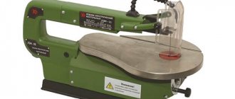
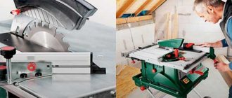
Making a stationary circular saw with your own hands
You can buy a ready-made stationary circular saw from 9 thousand rubles. It will ensure proper work safety and save time on sawing wood. But, you can not spend money and make your own machine according to drawings and blanks.
Circulation saw table
Despite the external complexity of the design, it is not so difficult to assemble it yourself at home. Any stationary saw model consists of several elements:
- table;
- disc with teeth;
- engine;
- adjustable side support;
- shaft
Complete compact installation
To assemble all the parts of the circular saw, prepare:
- metal sheet from 8 mm thick;
- metal corner 45 by 45 mm;
- electric motor;
- disc with teeth;
- ball bearing;
- welding machine;
- block of wood;
- a piece of plastic or leftover laminate.
To make all the elements correctly, you should choose a drawing that will indicate the dimensions of the table for a hand-held circular saw, as well as all other dimensions and materials for the work. Here are some examples of ready-made schemes:
A simple version of the tableDimensions of the disk for home toolsDetailed plan with all dimensions3D model of the table
The assembly of the structure itself will proceed according to a certain plan, regardless of the chosen scheme:
Illustration Sequence of work
The tabletop must be made strong and stable. Use sheet metal according to your dimensions
If you plan to install other devices on the table, then arrange a place for them using thick plywood.
When making a guide for a circular saw with your own hands, pay attention to its height. It should protrude 12 cm above the table
This way you will have the opportunity to process the boards in width and thickness. To make a guide, take two pieces of corner and a clamp.
Make the central saw adjustable in height.
For the motor, mount a separate platform on the same axis with the rocker arm. Fix it with a bolt with a diameter of 1.5 cm. Install a metal plate on the side of the saw, having previously made a hole in it through which the bolt with attached handles passes.
For more detailed instructions on making a stationary circular saw, see the video:
Watch this video on YouTube
a circular saw
We make a circular saw from an angle grinder with our own hands: drawings and production videos
To create a circular saw with your own hands, you need to prepare a grinder engine, a profile rectangular pipe and steel corners. To get a truly comfortable saw, it is worth considering a stop, an axis handle and rods for adjustment.
Here are some do-it-yourself drawings of a stand for an angle grinder. Using them you can assemble a stop that allows the saw to slide.
Option drawing for workAssembled equipment
The order of assembly of the stop will be as follows:
- Several metal angles are required for a standard "T" stop. Place them at a distance of 3-4 mm on each side of the disk.
- The edges at the bottom must be rounded to avoid scratches on the workpiece during operation.
- Attach the corners with cross braces to the bolts and nuts on the front and back. The slots are fixed with washers.
- Place a metal clamp on the body. At the rear, you fasten the elements so that the thrust post and the clamp become one.
- Drill 2-4 mounting holes in the gearbox housing. It is more convenient to do this in the disassembled state of the element.
After assembling the stop, make an axial handle and an adjusting rod. Watch the video on how to make a frame for an angle grinder with your own hands according to the drawings:
Watch this video on YouTube
After connecting all the elements, your homemade circular grinder will be ready. In addition to it, various parts can be made. Here are some photos of DIY circular saw accessories:
A simple stop made from a long wooden beam. A quick version of a table for a circular table. A cover for a disk with teeth. A convenient work table.
Headstock
Looking ahead, we note that both the front and tailstock include parts that can only be made with access to a metal lathe. Otherwise, it makes sense to think about purchasing ready-made modules, or at least their cast consoles.
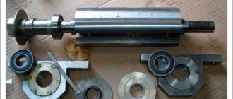
At the base of the headstock there are two bearing housings of types S, V or U, permanently mounted on an angle steel frame. Unfortunately, it is impossible to predict which sizes will be available, but in general, the height of the spindle axis above the bed should be at least 120 mm. Given that the diameter of the spindle shaft is about 25 mm, the most interesting would be the standard size of the bearing unit with a total height dimension of about 70 mm.
The shaft is machined from round carbon steel with a diameter of 40 mm with a tolerance of no more than 0.05 mm. There are two main variations of the shaft. The first is the simplest: the shaft pillar remains in the center, then descents are made to the landing diameter of the bearing units, then threads are cut at the ends. For axial fixation, four grooves are machined on the shaft for retaining rings.
1 — seats for bearings; 2 — grooves for retaining rings
The second variation has an extension in the form of a skirt immediately behind the cartridge thread. It is designed to install a flanged thrust bearing mounted on the boss of the headstock base. This approach allows you to reduce bearing wear if massive parts are processed on the machine.
The base of the headstock is two pairs of corners or two channels turned towards each other. By moving the vertical shelves together, you can adjust the height of the base to the axial height of the existing bearing units. A 45 mm strip is welded to the base below, which acts as an adjustment groove. The order of assembly is important: first, bearings are pressed onto the spindle, then the shaft is mounted on a frame with a backing of adjusting steel plates.
Device and characteristics
Selecting a milling machine is quite difficult if you do not understand its structure and basic characteristics. You need to know certain parameters on which the performance of all equipment will depend:
- power – it determines what types of workpieces can be worked with;
- overall dimensions of the equipment - depending on how much free space there is in the workshop, width, height and length are selected;
- the size of the work table - this characteristic affects what size metal workpieces are allowed for processing;
- length of guides for fixing the caliper;
- speed and type of spindle;
- control system.
There is also CNC equipment, that is, it is a computer-controlled mill. CNC stands for Computer Numerical Control. Such machines make production more productive and efficient. The operator sets a certain algorithm of operation, and the moving mechanisms themselves begin to perform the specified operations.
The design of industrial devices consists of a number of units connected to each other by wires and special fasteners.
- The bed is the basis of the turning and milling machine; all other elements are installed and secured to it.
- A support is a unit on which the cutters are attached. New machine models can have several cutters installed. This system allows you to perform work without additional operator actions.
- The spindle is a movable shaft with right and left rotation speeds.
- The tailstock is a machine component that is used to center or hold the workpiece.
The functions of lathes are extensive.
- Manufacturing of modules of complex shapes.
- Cutting a screw surface (internal or external).
- Longitudinal turning. The feed movement is carried out in a parallel direction relative to the workpiece axis. Here the cutting motion is fed to the workpiece and the feed motion is fed to the cutter.
- Cross turning. Can be radial or tangential. In the first case, the cutter feed occurs perpendicular to the axis (that is, in the direction of the radius). In the second, the cutter feed occurs transversely (along the chord).
- Milling. This is the processing of workpieces in such a way that the cutting mechanism makes rotational impulses, and the object of production makes translational impulses.
- Drilling and boring holes.
- Processing and grinding of surfaces, end parts, complex bends, holes.
Machine dimensions
In 90% of cases, finished machines have the following dimensions:
- length – 0.8 m;
- width – 0.4 m;
- height – 0.35 m.
The indicators allow you to work with wood pieces with a diameter of 25 cm and a length of up to 20 cm. In this case, you can not use the tailstock to improve fixation. It will be required if the length of the workpiece needs to be increased to 40 cm. A machine with such indicators is small, which allows you to install it in any convenient place in the workshop.
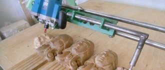
Do-it-yourself homemade lathe and copying machine with drawings
Buying an industrial copy lathe is not so cheap. Therefore, many craftsmen prefer to make it at home with their own hands. If you have certain knowledge and a drawing, this is not difficult to do. The capabilities of such equipment depend on the characteristics of the copier itself.
Required Tools
To make equipment, a turner will need the following tools:
- manual frezer;
- support made of plywood or metal;
- bolts;
- persistent bars;
- a pipe 2.5 cm in diameter to give direction for movement around the site.
The main tool when creating a copy lathe is a milling cutter.
Design elements
The main equipment spare parts that should be in a simple machine:
- bed;
- headstock and headstock;
- electric motor;
- master and slave centers;
- support for equipment.
The simplest model is made from a drill.
Manufacturing stages
The manufacturing algorithm for a turning unit is as follows:
- According to the finished drawing, it is necessary to manufacture the frame by welding. It must be reliable and withstand varying levels of vibration.
- Then install the electric motor. The optimal option is 200-250 W, rated at 1500 rpm.
- Attach the faceplate to the shaft.
This creates the basis of a standard machine. Then you should make the copier itself.
Creating a copier
Basic principles for making a copier that will help increase productivity when creating identical parts:
- you will need a hand router, and to install it, a plywood surface;
- holes should be made in the plywood platform to secure the bars;
- secure the bars with self-tapping screws;
- when making a copier, it is necessary to use a level, since even a small inaccuracy can lead to significant errors in the manufacture of the product;
- the platform must move without obstacles along the machine bed.
Installation of structural elements
After creating the copier, you need to install all the structural elements:
- Place the block horizontally and attach the template to it with self-tapping screws;
- The structure itself must be made in such a way that, if necessary, the copier can be tilted or moved aside and the machine can be used as standard turning equipment.
Horizontal block
This is an important element. The size of the block is ideally 3x7 cm. It is attached to vertical stands on a plywood platform using self-tapping screws.
Sample
The template is made from plywood. Attach it to the front of the beam. The upper platform must be checked for alignment with the axis directly on the template.
The edges must be treated with a sanding machine so that there are no nicks on them.
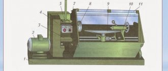
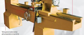
Small machine for home
almost finished machine and faceplate
We present a mini-lathe with dimensions of 800 x 400 x 350 mm. On it, they process parts with their own hands up to 25 cm in diameter and up to 40 cm in length.
Design elements:
- electric motor from the pump;
- front pillar - high-power electric sharpener for a couple of stones;
- caliper with support and adjustment;
- the frame is welded from a metal profile;
- the rear pillar is an element of a drill.
You will need plumbing equipment:
- electric drill;
- angle grinder;
- file;
- welding machine.
It is necessary to purchase additional materials:
- metal corner and channel;
- piece of block, plywood 10 mm;
- two pipes with such diameters that they are placed coaxially;
- metal strips 20 and 40 mm;
- fasteners;
- drive belt (from the car).
Assembling a homemade lathe:
- Choose a sharpener with your own hands so that you can use it without modifications. The axle must be placed high, with sealed bearings and washers to secure the discs. We install disks for adjusting the speed of movement on one of the axis outputs, and a faceplate for the workpiece on the second.
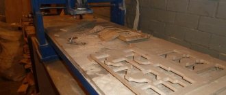
- The bed consists of two parallel channels, between which there is a gap - a guide. The length of the guide is equal to the length of the workpieces. At one end we weld a channel in the shape of a P, on which the headstock will be installed. The second end can be closed with a corner.
- The machine support is a stand of two pipes inserted into one another to adjust the height. At the desired height, the structure is fixed with a bolt. A horizontal bar is welded as a stop. Weld the stand with your own hands to the base using two corners secured to the guide using a pressure plate and a bolt with a nut. To correctly select the rotation speed of the part, use the drawing. It is most convenient to take a pair of intersecting values. For smaller jobs on particularly hard wood, you can remove the belt and use just the sharpener motor. That is, it is possible to work with several rotation speeds.
- The drive pulley is made from an old drill chuck. The driven pulleys are cut out of thick plywood, glued in two layers. We also make the faceplate from plywood; we pre-cut holes in it for the self-tapping screws that will hold the part. The faceplate is screwed onto the front pillar axle with the part already attached.
- We install the metal base on two supports. On the side of the headstock we make a platform of thick plywood on which the electric motor will be placed. To be able to change the belt tension, the motor is attached to a small plate, which can be moved around the site and secured in the right place.
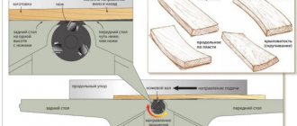
caliper and tailstock relationship between rotation speed, part diameter and material hardness
Stages of polishing work
Sanding wood
The polishing process itself is carried out in three rather complex stages.
Stage No. 1
At the first stage, before polishing, it is necessary to prepare the surface:
- sand the wood;
- remove all dust and lint from it;
Stage No. 2
The second stage will be priming the prepared wood. It must be carried out using varnish and a woolen thread swab or, in the absence of one, you can take a cotton one and wrap it in linen cloth. Why should you choose linen fabric? Because only this fabric does not leave small fibers. Cotton fabrics are absolutely unsuitable for this process, as they leave fluff, which is unacceptable during the polishing process. Remaining on the surface of the wood, they will noticeably spoil the appearance of the product.
Waxing wood
Modification options
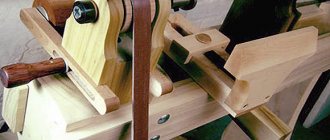
The simplest way to assemble a homemade lathe was described above, however, there are various modification options, it all depends on what parts you have at your disposal.
- instead of a workbench or table, the base can be a wooden beam or a metal structure;
- a clamp for a drill, instead of a clamp and a clamp, can be constructed from 3 pieces of plywood, connecting them in such a way as to form a structure in the form of the letter “P”, and attach a seat under the neck of the drill to it;
- if you have a welding machine, then it is quite possible to independently weld the tailstock from 2 bearings, 3 bolts, several nuts, 2 short sections of water pipe and a piece of sheet steel;
- If we construct a special copier attachment for our homemade machine from a drill, then it will be possible to make entire batches of identical parts at home using one template.
Introduction
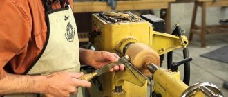
Using a wood lathe, you can make various blanks and finished products - these include various sticks, cylinders, plates, barrels, etc., which can be used in construction, repairs, in the manufacture of various decorative products, modeling, etc. Buying a large lathe - a troublesome and expensive matter. Below is an option for making such a machine yourself from scrap materials. The entire creation process is divided into operations and for each of them there are photo comments, and at the end there is a full video of the entire process. Making a homemade lathe using a video will greatly simplify the understanding of the idea and technological solutions. At the end of the article there are drawings of a do-it-yourself lathe.
Safety rules when working with a wood lathe
This device can be hazardous to life and limb if not properly prepared. However, work becomes absolutely safe and comfortable if safety precautions are followed.
Preparation:
- The worker must be dressed in special clothing, have safety glasses and gloves.
- It is necessary that the workpiece has initial manual processing.
- There should be no unnecessary objects on the machine.
- Before work, you need to check the condition of all components of the lathe, especially the belt drive, spindle and button panel.
- The operation of the machine should be checked. To do this, you can let it run idle for a while.
- The tool rest should be installed at a distance of 2 to 3 cm from the workpiece.
In progress.
- Under no circumstances should you stretch your hands towards the rotating workpiece, tilt your head towards it too much, or move away from the operating machine.
- The chisel should be brought up smoothly, avoiding sudden movements.
- From time to time you need to turn off the machine in order to safely move the tool rest towards the workpiece, reducing the increasing distance between them.
After finishing work.
- It is necessary to turn off the machine and remove the finished product from it.
- Clean the chips using a special brush or other cleaning tools.
- Return used tools to their original places.
JET
| PWL-1440L | Max. workpiece diameter 350 mm | Max. workpiece length 1000 mm | In stock | 9 000 q 263 BYN 42,336 KZT 8,583 KGS 52,977 AMD $101 83 € |
| JWL-1220L | Max. workpiece diameter 305 mm | Max. workpiece length 510 mm | To order | 34,000 q 994 BYN 159,937 KZT 32,424 KGS 200,136 AMD $382,316 € |
| JWL-1220LVS | Max. workpiece diameter 305 mm | Max. workpiece length 510 mm | To order | 39,000 q 1,140 BYN 183,457 KZT 37,193 KGS 229,568 AMD $438,363 € |
| JWL-1015 | Max. workpiece diameter 250 mm | Max. workpiece length 370 mm | In stock | 46,000 q 1,345 BYN 216,385 KZT 43,868 KGS 270,772 AMD $517,428 € |
| JWL-1015VS | Max. workpiece diameter 250 mm | Max. workpiece length 370 mm | In stock | 52,000 q 1,521 BYN 244,609 KZT 49,590 KGS 306,091 AMD $584,484 € |
| JWL-1221 | Max. workpiece diameter 318 mm | Max. workpiece length 450 mm | To order | 66,000 q 1,930 BYN 310,466 KZT 62,942 KGS 388,500 AMD $742,614 € |
| JWL-1443LB-M | Max. workpiece diameter 370 mm | Max. workpiece length 1100 mm | To order | 67,000 q 1,959 BYN 315,170 KZT 63,895 KGS 394,386 AMD $753,623 € |
| JWL-1443L-M | Max. workpiece diameter 370 mm | Max. workpiece length 1100 mm | To order | 72,000 q 2,106 BYN 338,690 KZT 68,664 KGS 423,818 AMD $809,670 € |
| JWL-1421VS | Max. workpiece diameter 368 mm | Max. workpiece length 450 mm | To order | 96,000 q 2,808 BYN 451,587 KZT 91,552 KGS 565,091 AMD $1,079,893 € |
| JWL-1440VS | Max. workpiece diameter 370 mm | Max. workpiece length 1016 mm | In stock | 120,000 q 3,510 BYN 564,483 KZT 114,440 KGS 706,364 AMD $1,349 1,116 € |
| JWL-1640EVS | Max. workpiece diameter 418 mm | Max. workpiece length 1000 mm | In stock | 180,000 q 5,265 BYN 846,725 KZT 171,660 KGS 1,059,546 AMD $2,023 1,675 € |
| JWL-1840EVS | Max. workpiece diameter 470 mm | Max. workpiece length 1000 mm | To order | 195,000 q 5,704 BYN 917,286 KZT 185,965 KGS 1,147,842 AMD $2,192 1,815 € |
| Powermatic 3520C | Max. workpiece diameter 508 mm | Max. workpiece length 910 mm | To order | 335,000 q 9,799 BYN 1,575,850 KZT 319,479 KGS 1,971,933 AMD $3,766 3,118 € |
| Powermatic 4224B | Max. workpiece diameter 610 mm | Max. workpiece length 1067 mm | In stock | 450,000 q 13,164 BYN 2,116,814 KZT 429,151 KGS 2,648,866 AMD $5,059 4,188 € |
We make a wood milling machine for a home workshop
Milling machines are necessary for working with shaped wood parts. They are used for flat milling and profile processing. Professional equipment is multifunctional and costs a lot of money, so more and more “homemade” people are assembling such equipment for workshops and garages on their own.
Small DIY milling machine
The set of homemade wood milling machines includes:
- Drive mechanism. This is an engine whose power ranges from 1-2 kW. With such a motor, you can use various tools to work with wood without fear of failure.
- Lift for adjustment. Typically, it includes a body, sliding skids, carriages, a fixing screw and a threaded axle. During operation, the carriage moves up and down, and a screw is needed to fix it at the required level.
- Support. The table is made from solid wood.
Before assembly, be sure to draw up a detailed drawing with all dimensions. For manual wood milling machines, you need to think through everything in advance down to the smallest detail.
3D model of a table for a manual machine Equipment components Dimensions of the working element Cutting on a milling machine
The sequence of self-assembly of a convenient and practical wood milling machine for a home workshop is described in the video instructions:
If you are thinking about buying your own equipment rather than assembling it yourself, then to understand how much a manual wood router costs, look at the table with models and prices:
| Model name | Specifications | |
| Milling table Kraton MT-20-01 | site size | 64 by 36 cm |
| possibility of vertical work | There is | |
| equipment weight | 15.7 kg | |
| Milling table Kraton MT-20-01 | ||
| Milling machine Corvette-83 90830 | engine power | 750 W |
| transmission type | belt | |
| spindle speed | 11,000 rpm | |
| vertical stroke | 2.2 cm | |
| spindle diameter | 12.7mm | |
| Milling machine Corvette-83 90830 |
Making a CNC milling machine with your own hands
You can make your own numerical control equipment with your own hands. To do this, select suitable drawings of a CNC wood milling machine. You will need to assemble the model with your own hands strictly according to them.
Ready-made machine for a home workshop Equipment components Detailed assembly diagram Model of multifunctional equipment
Wood milling machines must have great strength, so it is better to take a rectangular beam mounted on guides as a basis. The lifespan of home equipment and its performance depend on proper assembly. Watch the video instructions for making such a device:
Below are photos of finished models of CNC woodworking machines with your own hands from professional “homemade” ones:
Milling cutters for woodworking machines: features and varieties
The cutter must withstand high rotation speeds during operation. Only in this case will holes of the desired shape be obtained. All options are divided into several subgroups:
Cone-shaped. Used to process various types of wood at different angles.
Examples of various cutters
- Profile. Used to decorate elements.
- V-shaped. You can make holes at 45⁰.
- Rectangular - for creating grooves.
- Disk. Grooves of different sizes are cut out.
- Moulders for rounding edges.
- Rebated for working with quarters.
Below are photographic examples of cutters for CNC machines for wood, which are similar in principle to conventional ones, but have a “tail”:
Wood cutters
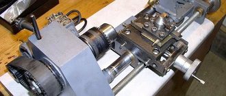
Types of lathes
A little theory about lathes. It will be useful to know about their main types, since a general understanding of these devices can broaden one’s horizons, increase the amount of knowledge in this area, and this, in turn, will allow operations to be carried out more boldly during work (it’s how it works: the more we know, the more We feel more confident).
- Screw cutting machine. Designed for processing metals (ferrous or non-ferrous), making cones and various types of threads from them.
- Revolving machine. It also has the purpose of manufacturing parts from metals. Works with calibrated rods, which are long metal sticks that can be processed.
- Carousel machine. Helpful when you need to work on large workpieces.
- Multi-cutting machine. It is very good to use for mass or serial production of parts, mechanisms, devices. They provide the ability to process a workpiece with several cutters at once.
- Machines with manual, foot and electric drive. The first two set the workpiece in motion by hand or foot, respectively. Such machines are well suited where there is no power supply. In the latter, the product is rotated by a motor that operates by supplying current to it.
There is also a classification of machines according to the material they can work with. Depending on this, these devices are divided into lathes for metal and wood. Today we’ll talk about the latter type, since in practice it is used most often in school and at home.
Types of woodworking machines
There are 3 types of lathes for wood processing. The differences lie in their purpose and main functions:
- industrial - units are used in enterprises, factories, and installed in workshops;
- semi-professional - machines are intended for use in small factories where production is carried out in small volumes;
- household (desktop) - devices are used for the manufacture of wooden parts at home.
Industrial devices show high performance. Their advantages:
- ability to perform a large volume of work;
- functionality;
- reliability.
The weight of the structure is from 200 kg, power – from 1 kW.
Semi-professional wood lathes are compact, weight 40-90 kg, power ratings 0.5-1 kW.
A household machine is used to process 1-2 parts at a time. The weight of the installation is 20-40 kg, power indicators are 0.2-0.5 kW. Units for home use have a minimal set of functions. There are differences in productivity and capabilities, as well as in the methods of performing work. Types of household machines:
- milling devices (used in 90% of cases for boring grooves);
- screw (threading, giving the part a cone shape);
- copy-milling devices (used to produce workpieces in non-standard shapes; specialized stencils are used for work);
- thickness planing (planing of boards).
CNC devices are also produced. These are automatic units that perform work stages according to a given program.
Tips for choosing
When choosing a turning and milling machine, you need to remember several features and recommendations.
- Mills with numerical control are suitable for industrial production. Working with them is faster and more accurate, and the manufactured elements will not differ.
- Frequently used equipment requires a cooling system.
- Units that can be connected to a 220V network are suitable for a private workshop or home.
- Additional equipment is selected depending on what material is to be processed. The cutters must be stronger than the parts being processed.
- Structural rigidity is one of the most important parameters. If the rigidity is insufficient, the processing speed of workpieces will decrease, which means productivity will also be low. If this parameter is neglected, the risk that the machine will begin to vibrate increases. Vibration can cause damage and shorten service life.
Tips for work
When performing assemblies in a home workshop, you need to follow the rules and follow the advice. Basic recommendations:
- the wooden workpiece should be positioned on the work surface so that it can rotate, but should not move;
- the workpiece must have the required shape before processing with cutters;
- Rasps are used to give shape (they need to be pressed flat).
You also need to remember that it is recommended to start processing work at low engine speeds in order to be able to eliminate all the imperfections of a wooden workpiece or piece of wood. Creating a machine or using a ready-made one requires a set of certain knowledge and skills, otherwise the functionality will not give the expected result.