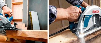
A proprietary guide bar for a circular saw costs almost as much as the saw itself. However, the device is very important. Why? When it is used, is it possible to do without it, is it possible to replace it with something or make it yourself? The circular saw guide provides certain benefits during operation. This article describes these benefits and also answers various related questions. Here we also consider making a guide bar with your own hands.
What's happened
The rip fence is also called a guide bar. Designed to make cuts strictly to a given size. It is called parallel because the thrust guide plane must in all cases be located strictly parallel to the plane of the saw blade. Otherwise:
- if the emphasis is “narrowing”, the disk will jam in the workpiece;
- “for expansion” - the disk will move away from the specified size, the cut will not be accurate.
The stops for manual and stationary circular saws are fundamentally different.
In the first case, the hand-held power saw itself moves along the workpiece.
When sawing on a stationary circular saw, on the contrary, the workpiece moves relative to the saw blade.
How is it different from a guide bar?
The guide rail is a more complex device compared to a one-sided stop. It is used only for hand-held circular saws, which move along the workpiece when sawing. Unlike the stop, they can limit the electric saw platform on both sides.
If, when sawing along a stop, a hand-held circular saw must be pressed manually so that it does not move away from the bar, then when sawing along a guide with a bilateral restriction, the saw goes strictly along it. This is a long device and is sold extremely rarely together with electric saws. Collapsible solutions consisting of several elements, which are connected along their length during operation, are also offered.
An example of such a tire is in the following video.
A rather flimsy device is shown. Suitable exclusively for thin workpieces. Under severe loads, the connections may crumble, the persistent plastic sides or the base itself may not be able to withstand. However, in some cases the device can serve and be beneficial.
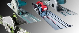
Solid, long aluminum tires are also available. When choosing, it is important that they fit the specific model of electric saw.
In addition, there are many design options for homemade guides for such tasks, with one- and two-way restrictions.
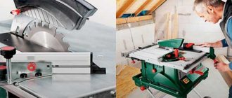
Model for hand-held circular saw
The stop is included in the sales package of almost all manual circular saws. Similar stops are used in conjunction with hand routers and jigsaws. They can have different designs: two pins and a short guide bar itself, or a bar on one plate.
Complete stop for Makita manual circular saw:
This stop is attached to the base of the electric saw itself and moves along the smooth edge of the workpiece (board, beam). Its use is limited - only on workpieces with at least one flat plane along which the guide bar can be guided.
There are also restrictions on the width of the workpiece. On a workpiece that is too narrow, it is also impossible to set such a stop; the smooth edge goes under the frame of the circular saw and is inaccessible to the guide bar.
It is also impossible to place such a stop on a board or sheet of plywood that is too wide, since the length of the pins or plate on which the stop bar rests is not long enough. In such cases, markings are used (pencil, marker) along which they are sawing, a guide bar or a separate bar along the entire length of the workpiece, which are not included in the electric saw kit.
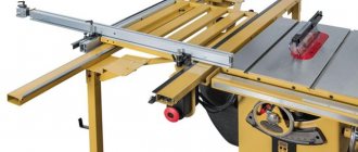
Model for a table-mounted circular saw
The guide bar (parallel stop) is mounted on the surface of the work table at the required distance from the disk. What is the distance of the bar from the disk, this is the width the workpiece will be cut.
When accurately installing the guide, plus/minus 1-2 mm. With a “wobbly” disk of large diameter – plus/minus 2-4 mm. Therefore, after a test cut, the width of the cut workpiece must be measured. Significant deviation from the specified width is possible.
This parallel stop is attached to the table in different ways:
- the table may have grooves for threaded clamps (bolts) to move the stop left/right;
- often the stop is attached to the table with clamps;
- There are models with a positioner. Its platform is attached to the edge of the table, and the bar extends from the platform and back on two guides.
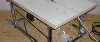
Parallel stops for the work table can be supplied as a set of stationary factory-made circular saws. On homemade circular machines, sometimes in addition to factory ones, guide bars are made on their own. It is not difficult.
Model for hand-held circular saw with table mount
When the hand saw is used as a stationary one, upside down and secured in the frame, the guides are used in exactly the same way as those described above for a stationary circular saw. If the hand saw is used in a normal manner, moving along the workpiece, the use of guides may vary.
- The parallel stop is attached to the workpiece being cut. For example, I press a corner to a sheet of plywood with clamps or a wooden block with self-tapping screws. Having made the cut, the stop is moved under the next workpiece.
- The workpiece is placed on the work table, and the workpiece and parallel stop are simultaneously secured to the table with clamps.
In all options, you need to carefully monitor where the circular saw blade will pass. Under no circumstances should it touch the edge of the work table or foreign objects when cutting. Having placed the stop, you should look down and once again make sure that the cut line will pass over the void.
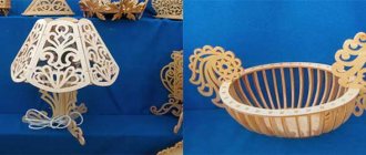
How to make it yourself
These simple devices are often made on their own. The peculiarity of homemade devices is that no two identical copies exist. Each master makes a device for his tasks.
Even if the product is copied in appearance and functionality, it will be unique. Differences will be in sizes, materials used, etc. devices are made for a wide variety of purposes and designs. Therefore, it makes no sense to provide drawings of any one device.
For hand circular saw
There is no need to make ready-made stops supplied in the kit. But when there is not enough length to cut wide workpieces, an analogue is made with longer pins or plates.
There is practically no need to do the simplest emphasis. Take a metal corner (25x25, 50x50, etc.) of the required length and 2 clamps for fastening it.
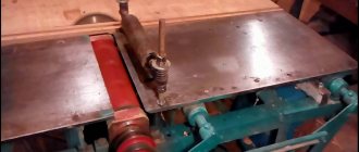
Making a guide bar with a two-sided restriction is a little more difficult. An example of this option:
An example of a simpler device with one-sided restriction
For circular saw
When cutting on a stationary circular saw, the workpiece itself moves relative to the saw blade. Therefore, guides are installed for the workpiece (board, timber). The difference from working with guides for a hand saw is that the stop does not need to be adjusted every time you need to cut many pieces of the same width.
For example, when it is necessary to cut 25X25 mm bars from a board 25 mm thick and 200 mm wide, the parallel stop is set 25-27 mm from both ends of the disk. At the exit from the disk, a minimum increase in distance of 0.5-1 mm is allowed.
If, on the contrary, there is a narrowing at the exit from the disk, the workpiece will jam and the material begins to burn from friction.
The most commonly used metal corner.
Such an emphasis can be either along the entire length of the desktop, or shorter, to the beginning-middle of the disk.
The first option is easily attached to the edges of the table using clamps on the edges of the table. To attach the second, shortened version, bolt holes are required in the middle of the table and in the rip fence itself.
In order for the stop to be moved, holes in the table or corner are made in the form of a groove, or I make a short groove in the corner and several holes in the table.
The front part of the shortened stop is attached to the edge of the table using a clamp or also using bolts through the slot holes.
An option shortened to the beginning, to a maximum of the middle of the disc, is preferable. Individual workpieces and boards may have internal stress. When cutting and leaving the disk, the sawn and remaining parts may begin to creep apart like a “yoke” due to the cut fibers and the released tension.
If the guide is shortened to the disk, the sawn parts after the disk will simply diverge in different directions. But if the rip fence reaches the end of the work table, then either the workpiece will begin to push away from the disk, or the disk will be clamped. This can cause the engine to stall, belts to slip, or wood to burn due to friction.
DIY making
First of all, they decide on what exactly is needed: a simple guide for the entire length of the workbench or up to the disk, or a stop-rail with one or two-sided limitation.
Available material is selected.
The guide must have an absolutely flat surface and be strong enough. Depending on the design of the guide, different materials are used:
- metal corners;
- rectangular pieces of plywood, fiberboard, plastic of sufficient strength and the required length;
- wooden blocks of suitable cross-section;
- metal profile, square or rectangle.
Next, the issue of fastening is resolved. To attach simple guides to a desktop or sheets, use clamps, threaded fasteners, and self-tapping screws.
As an example of fastening rectangular stops:
Here two bolts with a wing nut and plywood grips are used as clamps instead of clamps.
To fasten together parts of rail-type guides made of soft materials, suitable self-tapping screws of suitable length are used. If the ends of the screws extend beyond the thickness of the joint, they are cut off with an angle grinder using a metal wheel, or ground off on an abrasive wheel.
Design Features
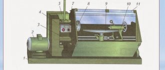
Immediately before work, you should figure out what parts the slide consists of and how they are connected to each other. The structure will be discussed using the example of a tenoning slide for a milling machine.
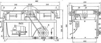
Dimensions, weight and general appearance
The size of the carriage is individual and largely depends on the specific saw, its cutting depth, as well as the purpose of use. Thus, the unit together with the tenoning guide can reach 800 kg. To avoid inaccuracies, experts advise making a design drawing.
Tool protection design
The tool protection is a separate structure, which contains a pipe and bracket, guide lines and a slider.
Advice! It is advisable to use a handwheel to control the movement of the protective ruler. Screws help install such a shield and fix it at the top and bottom.
List and location of controls
The compact control panel has:
- Button to turn on and off the drive.
- Mounting handles.
- Handle that clamps the spindle head.
- Spindle stop.
- Flywheel.
- Keys for fixing the ruler bracket.
- Colored light bulbs giving a signal.
Arrangement of components
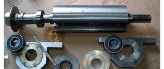
The main part of the structure is a cast-iron frame, a cast-iron table with rigid ribs and a moving carriage. The guide, in turn, consists of a plate, a clamp and a ruler, bearings and travel restrictions.
Component mechanisms and units of the unit
Composition of the spindle head:
- Cast iron body.
- Bearings.
- Spindle.
- Removable frame.
Drive parts in the equipment:
- Motor with 2 speeds.
- Spindle head.
- Connecting mechanism.
- The tile located under the motor.
- Poly V-belt transmission.
Kinetic scheme
When independently manufacturing a guide structure, the master needs to study the kinetic and electrical structure. The kinetic diagram describes the entire operation of the device - its parts and the relationships between them, the principle and sequence of actions.
The structure is manufactured in accordance with the kinetic and electrical circuit
Electrical diagram
An electrical diagram is a graphic document that identifies all the elements of a specific piece of equipment. In general, using conventional images, this diagram demonstrates the process of converting electrical energy, in particular, to activate the saw carriage.
Electrical equipment
The circular saw carriage is powered by an electric motor with 2 speeds, which is connected to the spindle through a belt. Due to this design, the latter is capable of accelerating in 2.3 seconds.
Important! The engine almost always has a protective mechanism to prevent overheating.