Purpose of the thicknesser
Homemade surface planers may vary in design , but they are all designed to produce wooden parts that are even in thickness. If a set of boards has different thicknesses, then using this machine you can bring the blanks to the desired thickness. You can also correct all kinds of wood surface defects.
Thicknessing machines are divided into two main types:
- Grinding.
- Cutting.
The basis of the machine is a U-shaped bed. A mandatory element is a shaft, which is attached to the bowl and fixed on a special beam. If the machine is cutting, then several knives are attached to the shaft to cut layers of wood as the shaft rotates. Grinding units use abrasive rollers that grind the part to the desired size.
The process of preparing for work
To adjust the thickness of the workpiece, the jointer must be lowered and raised (fixed). Therefore, our main task is to hang the electric planer above the tabletop.
You can, of course, do everything by eye, but it’s better to think through all the details in advance. You don’t have to make drawings of a mini machine yourself; you can search on the Internet. But I still recommend drawing out the products with your own hands and doing something based on the drawing. This way you will be able to think through every detail better, and you will be able to use everything that is not lying around in its construction :-)!
Classification and capabilities
Thicknessers are divided according to different criteria . Despite the fact that surface planers have the same purpose, they can be different in design.
The machines differ according to the following criteria:
- By drive. Some homemade devices are manually operated, but the most common ones are electric. In domestic models, the electric drive operates at 220 volts, while in professional models it operates at 330 volts.
- By type of feed rollers. The machine can be equipped with one or two pairs of drive rollers. If one pair is installed, then very strong pressure of the workpiece to the shaft is required. The disadvantage of this scheme is the possibility of vibration during processing. Systems with two pairs of feed rollers are more practical and convenient. They are used in cases where it is necessary to process a large volume of workpieces.
- According to the number of shafts with knives. Their number affects the variety of profiles that can be processed simultaneously.
- In terms of functionality. Some machines can do not only rough processing of the product, but also subsequent fine grinding. In this way, various chips, dents and other defects that inevitably occur when jointing technologies are violated or when the craftsman makes mistakes are removed.
- According to technical characteristics. Typically, these devices are designed for power from one to forty kilowatts with a cartridge speed of up to 12 thousand revolutions per minute. Thicknessers can process workpieces from five to one hundred and sixty millimeters with a planing width of up to 1350 millimeters.
Thicknessers may also differ in the way they regulate gaps and in the design of the bearing assembly on the main drive.
General concepts
A thickness planer is a special machine for smoothly leveling a wood surface.
This equipment performs a planing action called thicknessing. It was in honor of this action that the machine got its name. In turn, before planing the wood plane, it must be perfectly flat. This result is achieved using a jointer, which aligns the horizontal line on the tree. However, this work is considered rough.
Purpose
Thickness equipment has its purpose in many industries where wood is used. With its help, various shields, bars, and boards are processed. An ideal result is achieved in all planes of the product.
For example, if you take a wooden beam, then at the end of the planing operations it will be very smooth on all four sides. Thicknessers, in particular industrial ones, have the property of processing large areas and the number of boards that have a large width.
Homemade surface planers weigh quite little. This ensures their trouble-free transportation. On homemade machines it is much easier to regulate the thickness of the chips removed during processing.
Type of equipment
Thicknessing equipment is distinguished according to the following criteria, namely the number of knives on the cutting shaft:
Unilateral.
Thicknesser one-sided
This machine is the simplest and has only one knife on the main shaft.
Also, a single-sided thicknessing machine is considered a budget option and is intended for home work.
Due to one knife, it is capable of processing only one side of the product.
Double sided
Thicknesser double-sided
This equipment has in its design two shafts with knives located parallel to each other.
This module is considered more productive.
Has an automated supply of wood blanks.
Professional thickness planer
Thicknesser special
Such machines have in their design from three shafts with knives or more.
This thicknesser is intended for professional wood processing, and also has the ability to produce parts in large volumes..
The price category of this equipment ranges from 35 thousand to 100 thousand rubles. However, if the machines are created with the latest technology, then the price, accordingly, will be quite high. Therefore, it will be easiest and also cheaper to create your own project.
Advice: If your budget allows you to buy a factory installation, then you need to choose the best one. However, if the budget is tight, then try to create an analogue. This will save you time and money.
In addition to the knife differences, surface planers also differ in scope of application
Budget - household
With their help, it is possible to achieve good performance. It has an affordable price range and small dimensions. By purchasing this machine, you can easily build your own house.
Combined
Limited by small volume of work and low price. It is intended primarily for domestic purposes. For many household purposes, this equipment is quite sufficient.
Semi-professional
They are widely used in carpentry workshops. Such equipment is capable of producing impressive volumes of finished products.
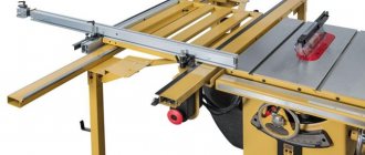
Professional thickness planers
Due to the fact that such equipment is more powerful than its smaller counterparts, it is capable of producing huge volumes of furniture blanks and components. They are used in woodworking factories.
Industrial modules
They are used only in sawmills, enterprises involved in the extraction and processing of wood. Such machines have huge dimensions and power, so using them in everyday life would be impractical.
Device and principle of operation
The standard machine can perform the tasks of a driven jointer and planer. The transverse machine can be used for short workpieces, and the longitudinal machine is suitable for long ones.
The simplest machine has a mandatory minimum set of components:
- An electric motor that rotates the shafts.
- A drive transmission, which can be a belt, gear, or, if the equipment is low-power, with replaceable pulleys.
- Shaft with knives. Knives can be of various shapes. Today, spiral-shaped knives are considered the best. During operation they create minimal noise.
- Upper assembly consisting of front and rear rollers. The first roller that encounters the workpiece has a grooved surface. Thus, it improves grip on the board and maintains the correct direction of movement of the workpiece. The second roller has a smooth surface so as not to spoil the processed part.
- Clamping unit. It removes chips and prevents the part from splitting. It is made in the form of a massive metal element with spring-loaded teeth or claw grips.
- Bottom node. He is responsible for feeding the block into the work area.
- A table with a unit for adjusting the gaps between the upper and lower level rollers.
- Bed. All remaining elements of the planer are placed on it.
Rotation from the machine's electric motor is transmitted to the working shaft using a drive transmission.
The blank board is placed in the working gap and pressed tightly against the lower unit. The part is then placed under the upper pressure rollers. The grooved roller grabs the front part of the board and feeds it to the working shaft. The upper and lower guides clamp the semi-finished product and fix the product during processing. The clamping device prevents the collection of chips.
When a part leaves the rear smooth roller, the next part is fed into the front one and thus ensures a continuous working process.
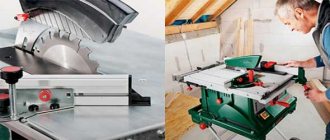
Assembly from an electric planer
It is difficult to work with a handheld device for a long time and productively, so many craftsmen assemble a surface planer from an electric planer with their own hands. The design is simple, it doesn’t require , and any craftsman can repeat it at home or in a small workshop.
To make a homemade surface planer you need the following tools:
- Lathe for turning rollers.
- Drilling machine for drilling holes for various fasteners.
- Welding machine to assemble the heavy frame and feed table.
- Drill. With its help, you can quickly drill small holes and tighten bolts.
- A grinder will be needed to cut out parts of the future machine according to the drawings. When working, you must not forget to make allowances for the thickness of the cutting blade of the grinder so that the design turns out correct and even.
Typically, the overall dimensions of homemade machines do not exceed 1x1 meters. Therefore, surface planers are easy to carry and place in any convenient and accessible places. The main thing is that the approach to them is always free.
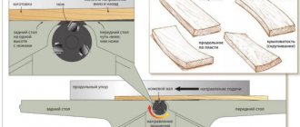
The layout of the main elements is as follows:
- Main table for feeding and dispensing the product (1)
- Actually, the wooden product itself (2)
- Fuse (3)
- Upper grooved roller that feeds the workpiece (4)
- Pressure block to ensure that chips do not get clogged (5)
- Main cutter shaft (6)
- Second clamping block (7)
- Upper smooth roller (8)
- Bottom roller with smooth surface (9).
First you need to assemble the frame. An iron angle or a profile square pipe with dimensions of fifty by fifty millimeters is perfect. The larger the size of these elements, the greater the possible vibration of a running machine.
After preparing the parts for the frame, the frame is assembled using a welding machine. Before doing this, you need to drill holes with a drilling machine. To dampen vibration, it is best to concrete the frame.
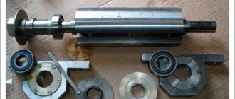
Shafts are made on a lathe: blade and auxiliary. If possible, it is better to purchase ready-made ones. The appearance of future products most depends on the quality of these elements.
The electric motor can have a power of four to five kilowatts. Gear options are suitable for motor pulleys and shafts. In this case, it can be used as a chain rotation transmission.
Pressure rollers are best obtained from a squeeze assembly from old washing machines. The rubber coating of these rollers is very gentle on the surface of the wood and does not deform it.
Using a welding machine, a frame for the rollers is created. The rollers themselves are secured with bolts. If springs are used on one side of the shaft, it will be possible to move the shafts vertically.
A welding machine will help make part of the steering rod - this will be a limiter. The tabletop is attached to the adjusting fasteners. It consists of a front and a back part.
Before starting work, check the correct location and sharpening of the knives.
After completing the assembly of the machine, you can begin setting up and checking its functionality.
Equipment setup
Before starting work, you must make sure that all fasteners are secure and that the bolts are sufficiently tight.
Adjust the machine by checking the degree of tension of the feed shafts. If the work table is completely full, increase the pressure of the front rollers.
When processing small elements, the pressure is reduced so as not to damage the wooden surface.
With a correct understanding of the operating principles of a thickness planer, its setup is quick and effective.
It must be remembered that for high-quality work it is not necessary to set the maximum planing depth. It is better to perform several operations in a row and then a good result will not be long in coming.
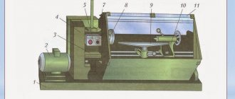
Equipment setup
The setup is carried out as follows. The support rollers (8) are lowered below the level of the table (10), and the tabletop itself is lowered so that a pre-treated wooden block laid on it passes freely under the blade shaft. Slowly raise the table, simultaneously turning the shaft until it touches the surface of the block. At the moment of contact with the upper edge of the knife shaft, the position of the table is fixed.
Having lowered the working surface by 0.3 mm, the block is moved under the rear clamp (3), which is adjusted with screws (2), trying to get the template to touch. Additionally, it is lowered by 0.7 mm (total 1 mm from the initial level) and the measuring stamp is placed under the front clamp (5), the height of which is set with adjusting screws (6) until it touches the bar.
Having lowered the working surface another 0.5 (1.5 mm from the initial level), adjust the rear pressure shaft (1). Continuing to lower by 0.5 mm, use the measuring template to change the height of the grooved feed roller (7). Lowering it another millimeter, the measuring template is placed under the claw protection and the height is adjusted until it touches. Finally, the support rollers are placed above the table surface.
Processing a workpiece that is not pressed simultaneously by both shafts is prohibited!
Depending on the model of woodworking equipment, the adjustment dimensions may vary. When starting to process coniferous species, the difference in the height of the pressure rollers is set within 0.3 mm, for hardwood – 0.1 mm. When planing workpieces, it is important to observe safety precautions, so you should not:
- place your hands near moving and rotating mechanisms;
- clean during operation;
- repair live parts.
To prevent the possibility of electrical damage, the equipment must be grounded. Before turning on, be sure to check the serviceability of all mechanisms.
Manufacturing of a grinding-thicknesser machine
You can make a simple grinding thicknesser yourself from a regular electric drill.
It just takes a little patience and time.
You will need the following parts:
- Electric drill or screwdriver.
- A sheet of plywood about fifteen millimeters thick.
- Nut with “ears”.
- M16 bolt and several self-tapping screws.
A small elongated frame is assembled from plywood, onto which a manufactured corner structure with a hole is installed at one edge. The assembled unit is a frame to which an electric drill is attached, and its chuck is inserted into the prepared hole.
After that, two side ones are cut out in the shape of an equilateral trapezoid, in which through holes are drilled for the axis of the future shaft. Landing bearings are inserted into these holes. The side frames are fixed to a plywood base on opposite sides. The elements are fastened using wood glue and self-tapping screws.
Then a lifting table is assembled on which the workpiece will slide. An adjustable lift is needed to change the distance between the table and the shaft. This distance determines the thickness of the part being processed.
The movable bed is attached to the main frame with a special guide.
The main shaft is assembled from several round pieces of plywood. The workpieces are glued together and the result is a grinding drum. The resulting shaft is carefully machined through with a drill. Then, using a circular saw, a longitudinal groove is made to secure the sandpaper.
A sheet of the required size is cut from a sheet of sandpaper and wound onto the shaft. The edges of the canvas are tucked into the groove of the shaft and secured to it with screws or self-tapping screws.
The finished emery shaft is inserted into the support bearings and the do-it-yourself thickness planer is ready.
general characteristics
Thickening is the final procedure that completes the work. The jointer will perform the initial processing, after which sanding is required. The thicknesser unit makes it possible to process large-width boards with maximum precision. This is what makes the machine popular; it saves time many times over.
On the market it is easy to find both industrial versions of equipment and small-sized devices used in small workshops. At the same time, home-made machine designs are also popular, the features of which are mobility and compactness.
A thickness planer costs a lot and purchasing it does not always make sense if it is not used regularly. Then they come to the decision to make a homemade thickness planer from a planing machine.
Many pioneers of homemade machines talk about their experience, share diagrams and drawings, according to which every person who knows a lot about technology can assemble their product.
But before starting assembly, prepare everything you need by carefully studying the design plan. Thickness planers are often produced by hand milling, and sometimes consist of an electric planer. When purchasing, you need to decide on its type in advance.
First you need to understand what a thickness planer is, what its components and components are. How to assemble correctly so that the mechanism performs the required task.