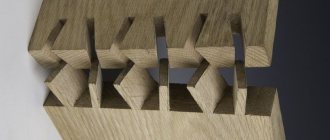
Simple Corner Joints
In this video, Celal Ünal demonstrated simple techniques for making corner joints for wood. This video shows the following carpentry joints:
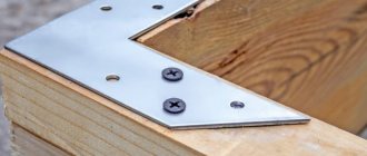
Connection with hidden screws
Miter spline connection
3. Miter connection reinforced with round tenons
Miter connection reinforced with dowels
5. Miter connection reinforced with oblique keys
Tongue-groove box connection
7. Miter connection with imitation dovetail connection
8. Dovetail joint with beveled edge tenons
And also how homemade devices were made to work with certain connections.
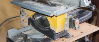
Creating tenons on bars and boards
Processing is performed using the following sequence of actions:
- The part to be processed is mounted on a plane from the bottom side.
- The edge of the part where the tenon is formed accommodates the cutouts at the guides at the top. The structure moves inward until it hits the end.
- A movable type element must be fixed while maintaining a certain position.
- We use a wedge tool to connect the guides and the plane located at the top to each other.
- Connection of a hand router with the upper guides.
- Using a router tool on a home router table, wood is removed from one side.
- When the first side of the workpiece is processed, begin the second.
The operation will be successful only with high performance and accuracy parameters. Setup refers to the required steps before the instruments are turned on. To resolve the issue, actions are performed in the following sequence:
- The milling tool is lowered until it reaches the surface of the base.
- Measuring the thickness of a part.
- The thickness result is divided by 4. The result is the distance parameter that is maintained when lifting the cutter above the base.
Joinery Joints by Luke Peterson
Some joinery joints from aspiring Australian woodworker Luke Peterson
Tenon and groove with dowel reinforcement
With two through dowels
With one through dowel
Dovetail with different sized spikes and rounding
Handcrafted dovetail with rounded edge. The wood creates a natural color gradient, moving from longitudinal to end grain.
Marking and making a tenon
To ensure the reliability of the structure, the manufacture of a tenon must begin with careful markings. At the first stage, it is determined what type this element will be manufactured and where it should be located. According to its location, positions are distinguished: corner end, middle and box. In addition, you need to decide how many of them will be in the connection. One of the factors influencing the quantity is the thickness of the workpiece. If the part has a thickness that does not exceed forty millimeters, choose a connection with one tenon. If the width is in the range from forty to eighty millimeters, two or three are made. For thicker workpieces, a triple or multiple connection is cut. The experience of professionals shows that the tenon should have a thickness equal to one third of the total size of the part, and the length should be equal to the thickness of the elements being fastened.
The main stages of making a spike are:
- marking the future spike (horizontal and vertical);
- tool preparation;
- sawing;
- cleaning the walls;
- fit.
Marking the locations of the required cuts is done using measuring tools in both planes. The choice of cutting tool depends on the capabilities of the manufacturer. At woodworking enterprises, this operation is performed on special machines. If you plan to make a tenon with your own hands, use ordinary saws. The most suitable are: a bow saw or a hacksaw. After making the spike, its surface is cleaned. This is done using files and sandpaper. Next, the insert tenon is adjusted to fit the prepared groove. After completion of this operation, its final fixation is performed.
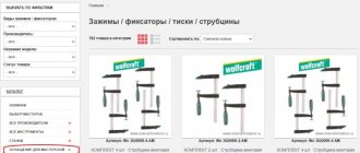
Rip fence
The most used device that comes with almost every router is a parallel stop, which ensures the straight movement of the cutter relative to the base surface. The latter can be the straight edge of a part, table or guide rail.
The parallel stop can be used both for milling various grooves located on the face of the workpiece, and for processing edges.
Parallel stop for a manual router: 1 - stop, 2 - rod, 3 - base of the router, 4 - rod locking screw, 5 - fine adjustment screw, 6 - movable carriage, 7 - movable carriage locking screw, 8 - pads, 9 - screw stop locking.
Edge routing using the rip fence
To install the device in the working position, it is necessary to slide the rods 2 into the holes of the frame 3, ensuring the required distance between the supporting surface of the stop and the axis of the cutter, and secure them with the locking screw 4.
To accurately position the cutter, you need to release the locking screw 9 and rotate the fine adjustment screw 5 to set the cutter to the desired position.
For some stop models, the dimensions of the supporting surface can be changed by moving or spreading the support pads 8.
If you add one simple part to the rip fence, then you can use it to mill not only straight, but also curved grooves, for example, to process a round workpiece.
Moreover, the inner surface of the block located between the stop and the workpiece does not necessarily have to have a rounded shape that follows the edge of the workpiece. It can also be given a simpler shape (Figure “a”).
In this case, the trajectory of the cutter will not change.
Of course, a regular rip fence, thanks to the notch in the center, will allow you to orient the router along a rounded edge, but the position of the router may not be stable enough.
Guide rail
The guide rail is attached to the table or workpiece using clamps or special clamps. The tire can be equipped with an adapter (shoe), which is connected to the base of the router by two rods. Sliding along the profile of the tire, the adapter sets the linear movement of the cutter.
Sometimes (if the distance of the tire from the router is too close), the supporting surfaces of the tire and the router may appear in different planes in height. To level them, some routers are equipped with retractable support legs, which change the position of the router in height.
Such a device is easy to make with your own hands. The simplest option is a long block secured to the workpiece with clamps. The design can be supplemented with side supports.
By placing a block on two or more aligned workpieces at once, grooves can be made in them in one pass.
When using a block as a stop, it is inconvenient to place the block at a certain distance from the line of the future groove. The following two devices do not have this inconvenience. The first is made from boards and plywood fastened together.
In this case, the distance from the edge of the stop (board) to the edge of the base (plywood) is equal to the distance from the cutter to the edge of the router base. But this condition is met only for a cutter of the same diameter.
Thanks to this, the device quickly aligns along the edge of the future groove.
The following device can be used with cutters of different diameters, plus when milling, the router rests on its entire sole, and not half, as in the previous device.
Slot milling fixture
Slot milling attachment
The stop is aligned along the edge of the hinged board and the center line of the groove. After fixing the stop, the folding board folds back, making room for the router.
The width of the folding board, together with the gap between it and the stop (if there is one), should be equal to the distance from the center of the cutter to the edge of the router base.
If you focus on the edge of the cutter and the edge of the future groove, then the device will only work with one diameter of the cutter.
When milling grooves across the grain, at the exit from the workpiece, when milling an open groove, cases of wood scuffing are not uncommon. The following devices will help to minimize scuffing: I press the fibers where the cutter exits, preventing them from splitting off from the workpiece.
Two boards, strictly perpendicular, are connected with screws. Different cutters are used on different sides of the stop so that the width of the groove in the fixture matches the width of the groove of the part being milled.
Another attachment for routing open slots can be pressed harder against the workpiece, which further minimizes scuffing, but it only fits one diameter cutter. It consists of two L-shaped parts connected to the workpiece with clamps.
Slot milling device Slot milling device
Copy rings and templates
The copying ring is a round plate with a protruding shoulder that slides along the template and provides the necessary trajectory of the cutter.
The copying ring is attached to the base of the router in various ways: they screw it into a threaded hole (such rings are in the photo below), insert the antennae of the ring into special holes on the base, or screw it with screws. Copy ringsInstalling a copying ring
The diameter of the copy ring should be as close to the diameter of the cutter as possible, but the ring should not touch its cutting parts. If the diameter of the ring is larger than the diameter of the cutter, then the template must be smaller than the finished parts to compensate for the difference between the diameter of the cutter and the diameter of the copy ring.
Routing an edge using a template and a copy ring
The template is secured to the workpiece with double-sided tape, then both parts are pressed with clamps to the workbench. Once you have finished routing, check that the ring is pressed against the edge of the template throughout the entire operation.
You can make a template for processing not the entire edge, but only for rounding the corners. In this case, using the template shown below, you can make roundings of four different radii.
First the corner needs to be sawed off. Rounding the corner using a template
In the figure above, a cutter with a bearing is used, but the template can also be used with a ring, only either the ring must exactly match the diameter of the cutter, or the stops must make it possible to move the template away from the edge by the difference in the radius of the cutter and the ring. This also applies to the simpler version shown below.
- Template for rounding cornersRounding a corner using a template
- Templates are used not only for milling edges, but also grooves on the face.
- Milling a groove using a template
- The template can be adjustable.
- Adjustable templateCutting groove according to template
- Template routing is a great method for cutting out hinge grooves.
- Template for milling grooves for hinges Milling grooves for hinges
Tools for milling round and elliptical grooves
Compasses are designed to move the router around a circle.
The simplest device of this type is a compass, consisting of one rod, one end of which is connected to the base of the router, and the second has a screw with a pin at the end, which is inserted into a hole that serves as the center of the circle along which the cutter moves. The radius of the circle is set by shifting the rod relative to the base of the router. Device for milling a circle
It is better, of course, for the compass to be made of two rods.