Design of a stationary circular saw
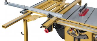
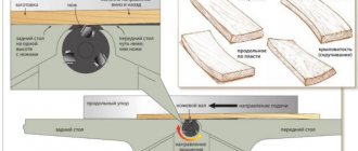
A stationary circular saw is designed to perform fairly large volumes of work. The design of the implemented option in two forms is presented in the diagram below. It also shows the main dimensions of the installation, which are recommended to be used as a starting point for self-assembly.
In the drawing, the numbers correspond to the following structural elements of homemade equipment:
- 1 – frame (bed);
- 2 – side panel;
- 3 – starting device;
- 4 – mechanism for adjusting the height of the table, 13 – its stops;
- 5, 6 and 7 – two halves of the sawing table with a base;
- 8 – electric motor;
- 9 – platform for installing the motor;
- 10 – studs (M10);
- 11 – saw;
- 12 – shaft;
- 14 and 16 – driven and driven pulleys, respectively;
- 15 – belt;
- 17 – switch.
It is better to place the starting device in a visible place on the panel (made of dielectric material) so that access to it is free. It is also recommended to equip the machine with an emergency switch. It is convenient when it is large in size.
Focusing on your own needs, you can improve the unit by making it with a jointer or planer. To do this, it is enough to secure a drum with knives on the existing shaft, and make a slot of the appropriate size in the table for it. This will allow you to expand the functionality of the created installation: plan lumber on it, chamfer and select a quarter from wooden blanks.
If you plan to regularly perform carpentry operations using homemade equipment, it is recommended to equip it with a coordinate table with several guides. They need to be fixed at different angles. To organize productive work, it should also be possible to regulate the speed of the electric motor and quickly replace disks if necessary.
Do-It-Yourself Lifting Mechanism for Circular Paper
Stationary circular saw at home - according to our drawings and operation possible for everyone
A household often doesn't have enough of a circular saw.
, especially if a complete renovation or construction is underway. Industrial products are not available to everyone - they are very expensive. But of course, make the circular yourself, using the materials that are available in the household.
A stationary circular saw in artisanal conditions is created with advancement in several possible directions:
- adapting existing hand tools using the engine and circular saw for new abilities;
- improvement of industrial products to expand functionality;
- assembly from individual parts, made, for the most part, on their own.
A stationary circular machine includes several main components: a table, a shaft, a motor and some others, the properties of which are not so important.
Making a workbench with an integrated saw inexpensively and ruggedly
The table is used for mounting woodworking devices. It can be assembled entirely from metal, which is better, especially for machines with a high-power engine. Wood also makes excellent circular tables. However, you need to take into account that the tabletop should be covered with a sheet of metal, otherwise the wood will soon wear out. Tables must be rigid and stable, able to withstand heavy loads during work. The surface is made completely level, and protection shields must be installed above the rotating parts.
The motor from a washing machine is well suited for a homemade circular machine. Portable tools are less suitable: their commutator motors are designed only for short-term work. They have very high speeds, low efficiency, and are afraid of clogging. There is an option to use a three-phase electric motor; if the household does not have 380 V, it will be useful to purchase capacitors so that it can operate on 220 V.
The most critical component is the shaft. Use it ready-made, if available, or grind it from round metal. The work on the lathe is done in one setup, then the assembly with the working parts is inspected for centering. Even a small beat is unacceptable, otherwise it will become stronger during work when it is unacceptable to work. Seats are provided on the shaft: for a circular saw and for pulleys, and additionally. They also make grooves for planing knives.
The properties of a circular saw , a motor and the greatest thickness of lumber that can be cut are interconnected. The maximum speed for which it is designed is indicated on the purchased circular disk. The number of revolutions transmitted by the engine to the shaft is less. The motor power affects the very permissible diameter of the toothed saw. The diameter must be more than two or three times the thickness of the material; otherwise it will be difficult to saw. It is believed that to cut materials 100 mm wide, you need a motor with more than 1 kW of power.
READ DIY Hand Circular Saw Machine
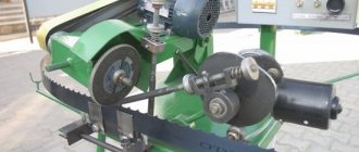
The transmission is made only by V-belt - if foreign objects get under the saw, the material jams, the belt slips on the pulleys. Injuries in this option are virtually eliminated. It is important to choose the right gear ratio. We take into account two indicators: engine speed and the very permissible number of revolutions of the circular saw . We calculate the required diameters of the pulleys. A pulley with a huge diameter is installed on the engine, and a pulley with a small diameter is installed on the circular shaft in order to increase the number of revolutions.
The revolutions of the shaft with a circular saw are not just as many times the motor revolutions as the diameter of its pulley is smaller than the diameter of the pulley on the engine.
To work with wood in large volumes, it is better to have a machine that allows you to cut the material, plan it, and select a quarter. A fairly powerful electric motor and a rigid table are required. We present a structure made of angle iron and steel. It provides a cutting depth of 60 mm, of course planing boards 200 mm wide. A three-phase motor of 1.1 kW, 2700 rpm is used. To connect to 220 V, capacitors are required.
1 – machine frame; 4 – panel; 3 – starter; 4 – device for height adjustment; 5.7 – desktop of 2 halves; 6 – base; 8 – engine; 9 – platform; 10 – M10 studs; 11 – circular disk; 12 – shaft; 13 – stops of the lifting mechanism; 14 – driven pulley; 15 – belt; 16 – drive pulley; 17 – switch.
Joiner machine, circular saw in handicraft conditions, lifting mechanism
conventional lifting mechanism
for
circular saws
. saw overhang is adjusted to every millimeter. production time approx.
A simple mechanism for lifting a circular saw
Mechanism shown
raising and lowering a homemade circular saw.
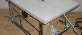
The desktop has dimensions of 700×300 mm. In the drawing we see that the height of the entire structure is 350 mm. The height is not enough for comfortable work; the circular saw will have to be installed on an additional platform; it weighs only 35 kg. You can increase the length and width, increase the height up to 1200 mm. We adjust other sizes to fit them, but the design features remain constant.
First, we make the bed frame from iron corners 25x25 mm. If we are not going to increase the height, we make the next similar lower frame. For a frame with a greater height, first we weld four legs from the same corners to the upper frame, and then we tie them at a height of 15–20 cm from the bottom. On either the upper frame there are grooves for the locking bolts of the motor platform. Two studs are welded to the rear side of the platform, which go into the holes on the rear part or the upper frame. By tightening the studs, we tighten the belts, then we lock the platform by tightening the nuts on the studs that go into the grooves.
READ How to Make Brakes on a Motoblock with Your Own Hands
To adjust the height of the table in relation to the saw, we use a light lifting mechanism
. It consists of racks, into the tops of which we cut grooves at an angle of 45°. A total of eight racks are needed - four on each side. We weld them to the frame with grooves located in a mirror image. We attach cross members to the outer posts. We drill holes in the middle of all of them and weld the nuts. Threaded shafts will move along them to regulate the lift.
Their ends rest against racks welded to frames assembled from 75x50 mm corners. On the side, we weld the studs opposite the grooves for the adjustment mechanism. The table consists of two equal halves and is attached to the frames with countersunk bolts. The adjustment mechanism works like this:
- loosen the nuts on the racks;
- we turn the screw, which presses on the stop, raising or lowering the table;
- tighten the stud nuts;
- We perform a similar adjustment for the second half of the working surface.
Functional woodworking machine
Of course, the design can be simplified without installing an adjusting shaft. Raise and lower the table manually. If you assemble the table not from 2 halves, but from a solid one, you will only need four stands for the lifting mechanism.
It is not difficult to turn a hand-held circular saw into a stationary one, expanding its capabilities. A table will come in handy right away. A comfortable material is Finnish plywood, which, unlike ordinary plywood, is laminated - the workpieces glide perfectly over the surface during processing. It is quite thick to withstand a lot of weight, waterproof, and easy to process. Ordinary 20 mm plywood is used, only it needs to be painted, or better yet covered with sheet steel, also called textolite.
It is necessary to realize that the depth of cut will decrease by the thickness of the cover. A disk with a huge diameter will come in handy so as not to reduce functionality compared to portable equipment. We make the dimensions of the tabletop sufficient to accommodate the width of the workpiece. It should be added that on a wide table you can additionally strengthen an electric plane and a jigsaw, which will make the machine universal.
Using the drawings and explanations, it is easy to make additional accessories for the circular saw that will expand its capabilities.
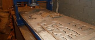
We mark a rectangle of the required dimensions on a sheet of plywood, cut it out, and process the edges. Using the sole, we apply a hand-held circular saw to the surface and mark the attachment points with a pencil. We make a slot for the circular saw. You can slightly deepen the attachment point using a milling cutter, but not more than 10 mm, so as not to weaken the tabletop. This production method will allow you to bring the cutting depth closer to that indicated in the circular saw’s passport.
We make a frame (tsars) from the boards, which we install from below to strengthen the structure. We fasten four boards into a box, glue them to the tabletop, securing them with clamps. We screw screws into the boards through the table. We countersink the holes for their production from above so that the heads of the screws are hidden. We attach the legs to the frames of the stationary saw, preferably with bolts, washers and nuts. The table should be provided with additional rigidity, so we make spacers at the bottom of the legs.
READ Miter Saw For Door Frame
We make a limit bar equal to the length of the working surface
. Here we drill two grooves perpendicular to the disk, where the bar will move and be fixed at a certain distance from the saw blade. It remains to make configurations in the control system: we secure the control button when it is turned on with electrical tape. We install a socket connected to the network on the drawer. We install a switch in the gap in the wire going to the saw.
It seems that the circular was not made perfectly; individual errors lead to the fact that its performance will be limited. This concerns, initially, essentially trifles. Let's start with the bearings for the shaft. Installing regular ones is justified if the machine is used occasionally. For a homemade device with constant use, it is better to install self-aligning bearings. They consist of 2 rows of balls and are adjusted by tightening the clamping nut. Be sure to install a cover to protect against dust and chips.
On the work surface
We apply a scale in centimeter increments. This will make woodworking much easier when determining the width of the cut. They are probably harassing the installation of a protective shield over the disk, but in vain - healing from chips getting into the eye, or in more severe situations, is more expensive.
When working with different materials, it is often necessary to adjust the speed of the circular saw
. The homemade design, you, does not have the ability to regulate the speed of the motor. There is only one way out - the use of pulleys of different diameters. They are installed on the motor shaft. If you decide to order pulleys from a turner, immediately make a solid pulley with two or three different diameters.
They probably want to install a three-phase electric motor on the sawing machine, without 380 V. Capacitors designed for a low operating voltage of 600 V, cardboard or oil-paper type, will be useful.
We calculate the capacitance of the capacitors from the power parameters of the electric motor: for 1 kW - 100 µF for the working capacitor Av. We take the capacity of the starting joint twice as large. The SB trigger is a button that automatically returns to its initial position. The start is normal: SQ is turned on, SB is pressed for a few seconds. After starting, the button is released when the engine picks up speed, of course, cut.
Source
Selection of materials and parts
When creating a homemade circular saw, it is necessary to maintain an optimal balance between its functionality, safety during operation and manufacturing costs. To achieve this, you should select materials and parts with the desired characteristics. To reduce costs, you need to start from old or unused equipment that is available.
Materials for making a bed with a table
To make a bed (frame), you can use a channel or metal corners (sizes from 25×25 mm to 50×50 mm are sufficient). If these materials are not available, then the most economical option is to purchase them at a scrap metal collection point. The legs of the machine will use water pipes or profile metal pipes.
When assembling the frame, it is also necessary to weld spacers at the corners to impart rigidity to the structure. To make it easier to move the machine, you can equip it with durable wheels (with a metal rim) equipped with locks. It should be borne in mind that the more massive the unit being created, the more stable it must be in order to avoid injury.
Metal pipe frame
The main requirements for a table for a circular saw: resistance to mechanical influences (vibration, shock), the ability to withstand workpieces weighing more than 50 kg without deflection, and surface smoothness . These properties characterize sheets of the following materials:
- become;
- duralumin;
- silumin;
- PCB;
- moisture-resistant plywood;
- organic glass.
If you use moisture-resistant plywood, then it should first be covered with zinc-coated sheet metal. The use of chipboard or OSB is not recommended due to the instability of these sheet materials to vibration influences.
Important! The strength of the table is of great practical importance. If it cracks or becomes distorted due to deflection, the disk may jam. This can lead not only to damage to the workpiece, but also to injury.
To carry out various work (for example, cutting logs into boards), you need to equip the table with a side support. It performs the same function as a guide bar for a hand-held circular saw: it ensures even sawing of lumber. Moreover, its use makes it possible to obtain workpieces of different sizes.
The guide stop must be strictly parallel to the disk to avoid jamming of the latter. It can be made from a wooden block or a metal corner. In the first case, only hardwood should be used. To be able to adjust the working gap, the stop must be removable. It can be fixed using clamps or in special grooves (bolts) made parallel to each other on the working surface of the tabletop.
Selection of engine and starting equipment
It is easiest to use a single-phase electric motor as a drive for the considered version of a homemade circular machine. Its power must be selected taking into account the upcoming load. Indirectly, you can navigate by the diameter of the installed disk:
- if it is 350 mm, then for normal operation of the unit you need an electric motor with a power of 1000 W;
- for a disk with a diameter of 170 mm, a 500 W motor is sufficient.
In the latter case, you can make a drive mechanism from an engine from an automatic washing machine. It is able to work for a long time at an average load level. For disks with a diameter of 350 mm, an electric motor from an industrial ventilation unit is suitable. It should be secured firmly to ensure proper engagement of the belt drive. For this reason, it will not be possible to reduce the level of vibration by installing the motor on shock absorbers: it will constantly oscillate.
Read also: How to make a tops shredder with your own hands
You can also equip homemade equipment with a three-phase electric motor (380 V) of suitable power. To start it from a 220 V network, you will need to additionally install working (phase-shifting) and starting capacitors into the electrical circuit. It should also be taken into account that the engine power will be less than the nominal value indicated on its plate or in the passport.
Starting equipment should be selected based on the power of the motor, on which the maximum current in the circuit will depend. A good option is to use a start button in conjunction with thermal protection - this will protect the electric motor from burning out the windings if the current increases when the disk jams . It is better to install the protection in a separate electrical panel attached to the side panel of the machine on the convenient side.
All connections must be well insulated so that the wires do not short-circuit to the frame of a homemade circular electric saw. The on and off buttons should be pressed without any effort. Due to the frequent storage of equipment outdoors, it is necessary to protect the electrical part well from getting wet. The simplest thing is to cover the installation with oilcloth or similar waterproof material.
Gear, shaft and disc
To transmit rotation from the electric motor to the disk, the best option is to use a V-belt in conjunction with pulleys from the car engine. The use of gears is not recommended for safety reasons. This is due to the fact that if the disk jams, the belt will simply slip, and the gear drive, due to its rigidity, can cause failure of the entire drive unit.
It is better to entrust the manufacture of the shaft to a specialist by ordering it from a professional turner. Moreover, when you plan to make a circular electric saw more functional by equipping it, for example, with a plane. But the simplest option is to buy a ready-made factory-produced part. A sample of it is shown in the photo below.
It is recommended to use self-aligning ball-type bearings together with the shaft. The mounts for them will fit from the car hub kit. In this case, the bearings should be well protected from dust.
It is easier to buy a disk for a circular machine ready-made than to make it from a sheet of tool steel. The problem is one of balancing. An imbalance of the saw during operation of the equipment leads to its rapid failure and reduces the level of safety of the work process. If you have a circular saw for wood, you can remove the saw blade from it.
It is necessary that the diameter of the disk corresponds to the corresponding parameter of the sawn timber: for example, for 100 mm logs you will need to use a saw measuring approximately 350 mm. This is due to the fact that the disk should not protrude more than a third of its diameter above the working surface of the table.
Ignoring this requirement not only leads to a deterioration in the quality of sawing workpieces, but also increases the possibility of injury.
Do-it-yourself parallel stop for a circular saw: types of design solutions
A circular saw is a convenient electric tool that greatly simplifies construction work and the process of cutting wood.
The equipment comes complete with various accessories that make the circular saw more convenient and safe to use.
But some of these accessories can be made with your own hands, so as not to spend extra money on them. Next we will describe how to make a parallel stop for a circular saw at home.
Rip fence for circular saw
What is a rip fence
A rip fence (or guide rail) is a small addition to your circular saw that allows you to make precise, straight cuts.
In simple terms, a rip fence is a stop that holds the circular saw in one direction, preventing it from leaving the desired cutting line.
Purpose of a rip fence for a circular saw
The rip fence is designed to create smooth cuts (for example, on plywood) parallel to the cutting saw blade.
Usually this device is already included in the standard configuration of a circular saw, but there are situations when the factory version is not entirely convenient for a particular user and cannot satisfy his needs.
Therefore, in practice, you have to make this device yourself, using simple instructions.
A natural question arises: why do manufacturers equip a circular saw with an inconvenient rip fence? This is done for safety reasons - using a device with a standard stop, you can make cuts whose width is no more than 25 mm. This is designed to ensure that the fence does not interfere with the movement of the circular saw guard.
Important! A parallel fence assembled at home will not limit the width of the cut.
List of necessary tools and materials for the stop
There are two simple options for making a rip fence with your own hands (without using bearings and other elements that complicate assembly). To select the desired design, you should determine the needs that arise when processing specific building materials.
For each design, you need to choose a strong rail, which will ultimately move along the working area of the table. To create a strong and reliable structure, it is advisable to use an extruded profile (magnesium or aluminum alloy) for assembly.
Important! The dimensions in the article will be given as approximate ones, since they need to be selected depending on the size of the saw itself.
Assembly material
Approximate dimensions of the aluminum corner used to create the slats:
- The wide part is 70 by 60 mm.
- The narrow part is 41 by 10 mm.
To make a rip fence for a circular saw with your own hands, you will need the following tools:
- A grinder with metal discs, which will be used to cut off excess parts of the corner.
- A file for cleaning cuts (it is advisable to process the metal immediately after cutting, so as not to cut yourself during assembly of the structure).
- To mark the future workpiece, you need to use any pencil, marker and center punch.
- A mandatory element for accurately marking the workpiece is a tape measure or meter.
- To create holes in the rip fence, you need to use a drill. The master chooses the diameter of the drill independently depending on the bolts that he will use in the future.
- Directly the bolts themselves that will fasten the parts.
- Several pins (8 by 18 mm).
- Tap (M5) for cutting threads (for the second design option).
This is the entire list of necessary materials and tools that you will need to use to create a rip fence at home.
Step-by-step production
The first design option is suitable for implementation if the work table for a circular saw has slots on both sides of the cutting blade, which are located parallel to its plane. If there are no slots, then it is advisable to immediately refer to the second instruction.
To begin with, the above-mentioned corner must be cut to a length of 450 mm. In order not to make a mistake with the markings, you need to place the metal on a work table with a circular saw so that the wide part of the bar is installed parallel to the cutting blade. The narrow bar should be placed on the table on the opposite side of the cutting blade.
On parts of the corner, 41 mm wide, it is necessary to mark a distance of 20 mm from the end in order to mark 3 holes with a diameter of 8 mm in the center. It is important to take into account that the distance between the holes is absolutely the same, otherwise they will subsequently have to be further adjusted to create alignment.
From the line of marked centers you now need to retreat 268 mm, where there will be three more through holes with a diameter of 8 mm (you need to mark with a center punch and then drill). This completes the marking process.
Hole marking
How to make a stop for a circular saw with your own hands - step by step assembly step:
- First of all, you need to drill 6 holes, which are marked on the workpiece with a center punch. Drill diameter - 8 mm. Afterwards, using a round file, it is necessary to thoroughly clean the holes being processed so that there are no burrs. Otherwise, the master will experience difficulties during the assembly process.
- Previously prepared pins measuring 8 by 18 mm must be placed in the outer holes.
- What happened was placed on the work table so that the pins fit into the grooves that are provided by the design of the work table for the circular saw. Place a narrow bar perpendicular to both sides of the working disk. You need to make sure that the device moves freely on the surface of the working area of the disk. The installed pins now serve as control elements that will prevent the cutting material from shifting from a certain area. This way, the parallelism of the planes will not be disrupted when working with a circular saw.
- Now you need to get to the desktop from below and find the middle hole, which was previously prepared for assembly. You need to carefully place M8 bolts between the pins so that the thread fits into the slot in the tabletop and the bolt heads rest against the bottom surface. They must be placed between the pins.
- On those parts of the bolts that will come out from the top side of the table, you need to screw an M8 wing nut and securely fasten it. Thus, a rigid connection of the entire structure with the desktop will be achieved.
Wing nut
After assembling the structure, you can proceed to work by performing the following procedure:
- The nuts are tightened until they stop to prevent the stop from moving while working with the saw.
- Move the rail to a certain distance from the disk (calculated depending on the material that needs to be cut).
- The rack is secured with the remaining nuts.
Now the created stop will move in a strictly defined direction, since the pins will not allow it to move to the sides. In this way, displacement of the material being processed relative to the cutting disc can be prevented.
The work of creating a rip fence for a circular saw with your own hands is completed. If necessary, you can also use the following design options. It will fit any desktop, whether it has grooves or not.
Important! All dimensions presented in the article are approximate, since specific figures can only be obtained by studying the parameters of the circular saw that is available in the house. The numbers can be easily changed proportionally depending on the specific brand of circular saw.
First you need to find a rail whose length is 700 mm. The preferred material for the corner is indicated above. On both sides of the angle (at the ends) you need to drill several holes suitable for M5 threads. A thread is cut in each hole using a tap.
Below is a drawing according to which it is necessary to make two guide lines.
Simple drawing
To do this, you need to use an equal angle corner measuring 20 by 20 mm. After cutting the material, it must be carefully processed with a file. Now you need to find the largest strips on the corner to drill holes there with a diameter of 5 mm:
- At the very top of the guide line.
- And also one hole in the center of the bottom strip.
Once the holes are ready, you need to use the tap again to cut the threads.
The preparatory process for the guides is completed; they need to be secured with M5 25 mm bolts with a cylindrical or hexagonal head. It is necessary to place M5 25 mm screws into the holes of the guides and secure them with any head.
Procedure for working with the created rip fence:
- Loosen the screws located in the holes of the end guides.
- The rack can now be moved to the required distance for optimal operation of the equipment.
- Once the rail is in place, each tightening screw must be securely secured.
The rail will move along the end planes of the circular table, which are parallel to the working disk. Since special guides were created located at the ends, the rail will move without distortion relative to the cutting disk, and therefore it will be possible to make the most accurate cut.
Important! To visually control the position of the stop according to the rules, it is advisable to apply markings to the table.
A manual parallel fence for installation on the working area of a circular saw cannot be made from scrap materials, and therefore you will have to buy some additional parts at a hardware store.
However, this equipment will soon pay for itself thanks to the precision of the work that the home craftsman receives (you won’t have to use extra wood to replace a damaged workpiece if the cut went to the side without a parallel stop).
Algorithm for assembling a homemade circular saw
The assembly of a woodworking machine according to the drawing given earlier is carried out in the following sequence:
- a rectangular frame is made from the corners;
- four legs are welded to it at the corners of the required height;
- at a height of about 200 mm from their lower edge, they make a binding from the corners;
- a shaft is mounted on the upper frame;
- fix the driven pulley on one side and the disk on the other;
- a table with a lifting mechanism is made and attached to the frame;
- on the lower frame they make a platform from corners or sheet metal for the electric motor;
- the drive pulley is fixed on the motor shaft;
- put the belt on the pulleys;
- On and off buttons and an electrical panel are mounted on the side panel of the unit;
- using wires of a suitable cross-section, connect the elements of the electrical circuit of the equipment (motor, buttons, protection);
- supply power to the machine from a stationary network.
The final stage is to check the functionality of the assembled equipment. First, you should make sure that all moving parts rotate freely: to do this, simply twist the drive pulley by hand. After which you can start the unit in test mode. If strong vibration is detected, you will need to check the reliability of the bolted connections and fixation of the disk.
You can make a circular saw with a table consisting of two halves or a solid one. In the latter case, you will need to cut a rectangular slot in it for the disk. The design of the machine with a table consisting of two halves is shown in the video below. This video also demonstrates the design of the lifting mechanism for these parts.
Important! To prevent the possibility of the saw jamming due to the connection of fragments of the workpiece being cut, it is recommended to install a riving knife. It should be located at a distance of approximately 3 mm behind the disc.
Table for hand-held circular saw with lifting mechanism
To change the depth of the cut, you can additionally install a lifting mechanism (elevator).
The lifting mechanism itself is mounted from a metal sheet that is attached to the frame on the machine. Lifting will take place along the guides by tightening the bolts.
One way is to install the adjusting rod with fixation nuts. Instead of rods, we use studs. The adjustment handle is made from a plate welded to the end of the stud. At a distance of 4–5 mm from the center we make holes for self-tapping screws. We weld a rod to the edge of the plate, which we will use to rotate the structure.
Recommendations for simplifying the assembly process
To regulate belt tension, the electric motor must be installed so that it can be moved. The easiest way to achieve this is by creating larger slots than required for the motor mounting bolts. In this case, the expansion of the holes should be carried out in the direction of belt tension.
If you completely follow the drawing, you will need to make a more complex belt tensioning mechanism. The process will be carried out by pulling up the platform with the electric motor using studs and fixing it with locking bolts in the desired position (in the drawing these structural elements are indicated by the number 10).
The entire design and assembly process can be greatly simplified if you make a circular saw from a circular saw. In this case, there is no need to install a number of parts (motor, disk, shaft, belt, starter). But the capabilities of the created model will be limited by the power of the tool used.
In any case, a homemade circular machine must be grounded. It is also additionally recommended to install a residual current device or differential circuit breaker in the panel. These measures will protect against electric shock if the machine body is energized, for example, due to breakdown of wire insulation. It is better to select components for the electrical part of a circular saw so that they are suitable for repair and easy to maintain. Free access to equipment components will help you easily replace failed parts.
Read also: DIY garage lifting mechanisms
How to make a circular saw with your own hands from a hand-held circular saw
If a person lives in a private home or has a garden plot, then having a stationary circular saw in the home craftsman’s arsenal is not only better, but sometimes even necessary. Unfortunately, the price of an industrially made standard of such a saw does not correspond to the frequency of its home use, and for some Russians it is simply not affordable. At the same time, it is quite easy to make a “circular” with your own hands , using the drive of a sewing machine or an ordinary electric drill. But the quality of work performed and the range of operations performed depend almost entirely on the circular saw .
DIY stationary circular saw. detailed instructions
The presence in the household of the necessary minimum tools for simple work fully justifies the need to have a small box with the simplest tools in everyday use.
But when the need arises to carry out simple repairs or realize a long-standing dream of a small hobby, then the need arises to purchase or independently manufacture a simple but very necessary carpentry tool - a stationary circular saw.
The practical use of this kind of tools varies from one craftsman to another, but one thing everyone agrees on is that such a machine is simply necessary in a household tool park.
In practical terms, a stationary circular saw is needed:
- for longitudinal dissolution of wood;
- for trimming the edges of unedged boards to obtain smooth sides;
- to obtain planks, slats, and boards of equal size;
- for selecting a part of the board (quarter) to create a tight connection of the boards into a shield.
- In purely economic terms, a circular saw is simply necessary for cutting firewood from wood processing waste.
Bed design
circular saw frame , the drive power of which does not exceed 0.8...12 kilowatts, is quite easy to make with your own hands from thick plywood and wooden blocks. For the drive, you can use an electric drill “BOSCH GSB 19-2” (power 0.85 kilowatts) or “DWT SBM-1050” (power 1.05 kilowatts), which is attached to under the stove using a special bracket. The length of the bed will depend on the length of the material being cut. For the table, you must purchase bakelite plywood with a thickness of at least 50.0 millimeters. Of course, a wooden bed is not suitable for professional work, but in order to unravel boards and quickly saw through bars, such a homemade design is quite sufficient.
In general, the bed will consist of a base and a tabletop ( desktop ). Of course, when manually making a circular saw , you must strive to simplify the design as much as possible. The design of the work table will primarily be determined by the design of the cutting blade mounting unit. Homemade circular devices use either a circular disk mounted directly in the chuck of an electric drill, or (more preferably) a two-support shaft driven into rotation by an electric motor through a belt drive.
It’s hard to imagine a carpentry workshop without a circular saw, since the most basic and common operation is longitudinal sawing of workpieces. How to make a homemade circular saw will be discussed in this article.
Introduction
The machine consists of three main structural elements:
- base;
- sawing table;
- parallel stop.
The base and the sawing table itself are not very complex structural elements. Their design is obvious and not so complicated. Therefore, in this article we will consider the most complex element - the parallel stop.
So, the rip fence is a moving part of the machine, which is a guide for the workpiece and it is along it that the workpiece moves. Accordingly, the quality of the cut depends on the parallel stop because if the stop is not parallel, then either the workpiece or the saw blade may become jammed.
In addition, the parallel stop of a circular saw must be of a rather rigid structure, since the master makes efforts to press the workpiece against the stop, and if the stop is displaced, this will lead to non-parallelism with the consequences indicated above.
There are various designs of parallel stops depending on the methods of attaching it to the circular table. Here is a table with the characteristics of these options.
| Rip fence design | Advantages and disadvantages |
| Two-point mounting (front and rear) | Advantages: · Quite rigid design, · Allows you to place the stop anywhere on the circular table (to the left or right of the saw blade); · Does not require the massiveness of the guide itself. Disadvantage: · For fastening, the master needs to clamp one end in front of the machine, and also go around the machine and secure the opposite end of the stop. This is very inconvenient when selecting the required position of the stop and with frequent readjustment it is a significant drawback. |
| Single point mounting (front) | Advantages: · Less rigid design than when attaching the stop at two points, · Allows you to place the stop anywhere on the circular table (to the left or right of the saw blade); · To change the position of the stop, it is enough to fix it on one side of the machine, where the master is located during the sawing process. Disadvantage: · The design of the stop must be massive in order to ensure the necessary rigidity of the structure. |
| Fastening in the groove of a circular table | Advantages: · Quick changeover. Disadvantages: · Complexity of design, · Weakening of the circular table structure, · Fixed position from the line of the saw blade, · Quite a complex design for self-production, especially from wood (made only from metal). |
In this article we will examine the option of creating a parallel stop design for a circular saw with one attachment point.
Preparing for work
Before you begin, you need to decide on the necessary set of tools and materials that will be needed during the work process.
The following tools will be used for work:
- A circular saw or you can use a jigsaw.
- Screwdriver.
- Grinding machine.
- Grinder (Angle grinder).
- Jigsaw.
- Hand tools: hammer, pencil, square.
During the work you will also need the following materials:
- Chipboard.
- Plywood.
- Solid pine.
- Steel tube with an internal diameter of 6-10 mm.
- Steel rod with an outer diameter of 6-10 mm.
- Two washers with an increased area and an internal diameter of 6-10 mm.
- Self-tapping screws.
- Wood glue.
Design of a circular saw stop
The entire structure consists of two main parts - longitudinal and transverse (meaning relative to the plane of the saw blade). Each of these parts is rigidly connected to the other and is a complex structure that includes a set of parts.
The main technological solution of this stop is the principle of jamming using an eccentric and tightly pressing two transverse guides with an oblique end.
Fixation occurs by turning the eccentric mechanism.
The pressing force is large enough to ensure the strength of the structure and securely fix the entire rip fence.
Read also: What slope should a sewer pipe have?
The entire design is not trivial and consists of a large number of different parts, each of which has its own purpose and size.
From a different angle.
The general composition of all parts is as follows:
- Transverse part
- The base of the transverse part;
- Upper transverse clamping bar (with an oblique end);
- Lower transverse clamping bar (with an oblique end);
- End (fixing) strip of the transverse part.
- Longitudinal part
- Planar sliding element (laminated chipboard, 2 pcs.);
- The base of the longitudinal part;
- Clamp
- Eccentric
- Eccentric handle
Making a circular saw
Preparation of blanks
It all starts with the fact that it is necessary to cut the workpieces to the specified dimensions.
A couple of points to note:
- flat longitudinal elements are made from laminated chipboard, and not from solid pine, like other parts.
- Two blanks of clamping strips are made with “oblique” ends (not 90º, but 63.5º).
Thus, we get the following set of blanks.
Eccentric clamp
Let's start making an eccentric clamp that rigidly fixes the guide.
We glue two blanks measuring 80x80 mm together.
Press with a clamp and let the glue dry. In the toga you get something like this.
Using a 22 mm feather drill, we drill a hole in the end for the handle.
In the center of the workpiece you need to make a blind (not through) hole 5 mm long.
It is better to do this by drilling, but you can simply hammer it with a nail.
The circular saw used for work uses a homemade movable carriage made of laminated chipboard (or, as an option, you can whip up a false table), which is not too bad to deform or damage. We hammer a nail into this carriage in the marked place and bite off the head.
Thus, we have an improvised axis of rotation for our part, called the “eccentric” (although in this case, the filled hole is located strictly at the geometric center).
Then, putting the workpiece on an axle made of a nail, we begin to grind off the corners and excess material.
As a result, we get a smooth cylindrical workpiece that needs to be processed with a belt or eccentric sander.
We make a handle - it is a cylinder with a diameter of 22 mm and a length of 120-200 mm. Then we glue it into the eccentric.
Transverse part of the guide
Let's start making the transverse part of the guide. It consists, as mentioned above, of the following details:
- The base of the transverse part;
- Upper transverse clamping bar (with an oblique end);
- Lower transverse clamping bar (with an oblique end);
- End (fixing) strip of the transverse part.
Upper transverse clamping bar
Both clamping bars - upper and lower - have one end that is not straight 90º, but inclined (“oblique”) with an angle of 26.5º (to be precise, 63.5º). We have already observed these angles when cutting the workpieces.
The upper transverse clamping bar serves to move along the base and further fix the guide by pressing against the lower transverse clamping bar. It is assembled from two blanks.
They are collected with glue.
And they are additionally fixed with self-tapping screws.
Lower transverse clamping bar
The lower transverse clamping bar is rigidly fixed to the base and serves to fix the guide by pressing against the upper transverse clamping bar.
Like the top bar, it also consists of two blanks.
We also assemble using glue and screws.
Both clamping bars are ready. It is necessary to check the smoothness of the ride and remove all defects that interfere with smooth sliding; in addition, you need to check the tightness of the inclined edges; There should be no gaps or cracks.
With a tight fit, the strength of the connection (fixation of the guide) will be maximum.
Assembling the entire transverse part
The cross guide bar of the cross guide is directly fixed to the circular table.
A transverse base is attached to this bar.
We assemble the entire structure using glue and screws.
Longitudinal part of the guide
The entire longitudinal part consists of:
- Planar sliding element (laminated chipboard, 2 pcs.);
- The base of the longitudinal part.
Planar sliding element
This element is made from laminated chipboard because the surface is laminated and smoother - this reduces friction (improves sliding), and is also denser and stronger - more durable.
At the stage of forming the blanks, we have already sawed them to size, all that remains is to refine the edges. This is done using edge tape.
The technology for edging chipboard is simple (you can even glue it with an iron!) and understandable.
The base of the longitudinal part
The base consists of four longitudinal elements, as well as two vertical ones for installing an eccentric.
If you break it down into details, you get the following diagram.
We collect the previously sawed blanks for glue.
We also additionally fix it with self-tapping screws. Do not forget to maintain a 90º angle between the longitudinal and vertical elements.
Assembly of transverse and longitudinal parts.
First you need to attach the substrate (longitudinal element) to the upper transverse clamping bar.
We fix it with glue and screws.
It's VERY MUCH here . It is important to maintain an angle of 90º, since the parallelism of the guide with the plane of the saw blade will depend on it.
Then we install the longitudinal base on the substrate.
We also fix it with glue and screws.
Installation of the eccentric
The eccentric is installed between two vertical elements on the longitudinal part.
A metal tube (future bushing) with an internal diameter of 6-10 mm must be placed in the eccentric itself.
We fix it with glue.
In addition to the bushings on the eccentric itself, you need to make similar bushings on the vertical elements, although, as an option (worst), you can use larger washers.
Additionally, a thrust block must be installed for better clamping.
Installing the guide
It's time to attach our entire structure to the circular saw. To do this, you need to attach the cross stop bar to the circular table. Fastening, as elsewhere, is carried out using glue and self-tapping screws.
We install the moving part.
All that remains is to check that the angles are correct, and we consider the work completed.
... and we consider the work finished - the circular saw is ready with your own hands.
How to design a table for a circular saw with your own hands with a lifting mechanism
Most people who work professionally with wood would like to have all the necessary machines at their disposal. But unfortunately, this is not always possible. Some people don't have the space to do it, others, and I think the majority, it's money. Any, even the most primitive machine is quite expensive.
But what’s stopping you from just doing it yourself? Nothing is impossible for a person with intelligence. For every carpenter, a circular saw is the main tool. But it happens that only a hand saw is available, and this is not always convenient for large volumes of work. In order not to purchase a separate tool, you can make a stationary mini saw yourself for ease of work - make a sawing table (stand) for it.
Table saw
When choosing a circular saw, you need to be guided by the following characteristics:
- Saw power. If the amount of work is quite large, it is advisable to take a tool with a power of at least 1.2 kW.
- Cutting depth. The thickness of the material to be processed depends on this parameter. For hand saws it is 40–70 mm. But when installing it in a table there will be a decrease of around 10 mm.
- Button placement. The design of the sawing table must provide free and safe access to all control buttons, otherwise it will be necessary to modify the control system yourself.
- Rotational speed. For cutting wood, high rotation speed is preferred. This affects the cutting quality. For plastic, for example, this is not very good. Due to the high rotation speed of the circle, the plastic heats up. You need to choose average characteristics. 3-4 thousand rpm will be enough.
Do-it-yourself table for a circular saw, installation, fastening
To make the saw table itself, you will need to acquire materials that are sold at any hardware store.
We will need:
- plywood 15–20 mm thick;
- timber 50*50 mm;
- boards, approximately 50*100 mm;
- switch;
- socket;
- self-tapping screws;
- varnish;
- PVA glue;
- rollers;
- metal corners.
Making a workbench
- Mark and cut a tabletop of the required size from plywood. Clean the surface with sandpaper.
- At the bottom of the tabletop we mark places for holes for attaching the saw. To do this, you need to remove the blade and install the saw in the right place, making notes. The holes for the bolts are countersunk on the surface, and the heads of the bolts need to be sanded.
- If the material will be cut at different angles, the hole for the disk should be made in the shape of an inverted trapezoid.
- Mark the places where the stiffening ribs are attached to the tabletop (from below, at a distance of about 8 cm from the edge). The legs need to be secured to the ribs. The ribs are screwed on with self-tapping screws at intervals of 25 cm and glued with PVA.
- The legs are made from timber 100 cm long. Then a screed is made from timber for additional strength.
- To be able to adjust the height of the table legs, nuts and M14 bolts are attached from below.
- We fix the saw from below.
- We attach the socket to the inside of the table. From it we pull the wire to the switch.
- We make a parallel emphasis.
We cut two strips of plywood, the same length as the width of the table. The width of the stripes is 10 cm. We make the corners round. We sand both strips and fasten them with self-tapping screws. Then we cut two strips of the same length, but three times wider. We fasten them. This will be the guide. We fasten the stop and guide. We set a right angle relative to the disk. We attach the rollers.
Table drawings for a circular saw
There are other ways to make a stand for a hand-held circular saw with your own hands. Here are two more examples.
Blueprints
Table for hand-held circular saw with lifting mechanism
To change the depth of the cut, you can additionally install a lifting mechanism (elevator).
The lifting mechanism itself is mounted from a metal sheet that is attached to the frame on the machine. Lifting will take place along the guides by tightening the bolts.
One way is to install the adjusting rod with fixation nuts. Instead of rods, we use studs. The adjustment handle is made from a plate welded to the end of the stud. At a distance of 4–5 mm from the center we make holes for self-tapping screws. We weld a rod to the edge of the plate, which we will use to rotate the structure.