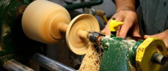
The first machine that every craftsman feels the need for is a tabletop drill, or simply a drill. But after purchasing it or making it yourself, it soon turns out that you need to sharpen something, and a lathe costs an order of magnitude more. The temptation is great to make a universal lathe like the one in Fig. below:
Homemade universal lathe
One can only take off one's hat to the ingenuity, skill and accuracy of such masters. Yes, you can also turn wood on a metal lathe; Many of these benchtop lathes come with inserts in the spindle chuck to hold the wood workpiece. But - alas! – a homemade universal lathe will not hold precision on metal for long.
The point is not only that the cutting force of metal is many times greater than that of wood. The physics of metal cutting itself is completely different. In order not to go into the basics, even a cursory superficial review of which would require an inordinate amount of space, let’s take it and compare it: have you seen a metal cutter as sharp as a chisel or a piece of iron on a plane? And what happens if you cut down a tree with a chisel? The drill can still cope with both materials: there the cutting force is symmetrically concentrated on the working body itself. But as for the metal point, the requirements for the machine tool, the requirements for the machine tool for it turn out to be such that machine tool building became a separate industry long before the industrial era. The best machine-building plant does not make its own machines - it’s too much for them. However, it is quite possible to assemble a wood lathe with your own hands, and in such a way that it will maintain the maximum achievable processing accuracy of +/–0.5 mm on wood for many years, if not decades. You still can’t do without 2-3 turning operations on metal (see below), but in this case they can be performed to order by a turner of 2-3 categories on a regular, not high-precision, machine, even if it’s a restored DIP. And, of course, you will need to buy a set of cutters for processing wood on a lathe, see figure. Everything else will not require any additional costs.
Set of cutters for processing wood on a lathe
History and evolution
Further in the text you will come across technical solutions that are effective, but little known to amateur craftsmen, because... in industry, for one reason or another, they are not used or are used to a limited extent. However, they can simplify and facilitate the manufacture of a homemade lathe for processing wood so much that in some cases it will be possible to limit the use of a power tool to a hand drill. The machine tool industry of the millennium is developing under the sign of solving the problem: how to make machine parts with an accuracy of, say, 1 conventional unit of length on a machine with an accuracy of, say, 0.2 of the same units? Etc. To understand how technology came to such a life, it will be useful to briefly turn to history.
The ancestor of all machines for processing materials by rotation is a device with which Neolithic people made fire and drilled horn, bone, stone, etc. 1 per rice; in the latter cases, an abrasive of wet quartz sand was added under a drill made of wood or bone. The primitive Celts, using the same principle, invented a foot-operated lathe, pos. 2; the centers were made from sharpened, burnt stakes of hard wood. In England, this unit is still used by furniture makers. The forest is not cut down there block by block. Having bought a couple of scaffoldings for felling, the master then carries armfuls of finished legs, balusters, etc. to the track. In a craft of this type, the machine survived for approx. until the beginning of the 18th century, pos. 3, although the workpiece rotates back and forth in it and the master has to be additionally distracted in order to turn the cutter over.
Stages of evolution of the wood lathe
In Ancient Egypt, already in the era of the Middle Kingdom, a lathe with a bow drive was well known, pos. 4. The “motor” was, naturally, the slave. In the Russian village community (in the world), with its strong traditions of mutual assistance and mutual assistance, the bow lathe survived in the outback until... the 80s of the last century! Mass individual wooden construction was in no way included in the five-year plans, but the Soviet leadership in the provinces turned a blind eye to unauthorized logging in limited quantities for their own needs or to unauthorized purchases of wild logs from timber industry enterprises for the universal Soviet currency of 40 volume. and a capacity of half a liter.
For fine and/or small work, a foot machine with a string and a bow machine were not suitable: there are always inhomogeneities in wood, and the workpiece itself was the flywheel - the damper of torsional vibrations. Radical improvements to the lathe were introduced by the master Theodore in Ancient Greece approx. in 400 BC uh, pos. 6. He supplemented the foot drive, firstly, with a crank - now the workpiece rotated in one direction. Secondly, I made the centers rotating and equipped one of them with a grip to hold the workpiece. Thirdly, he introduced a heavy flywheel into the kinematic scheme. Individual machines of this design were in operation at industrial enterprises before the start of electrification of industry, pos. 7 – given the complete absence of social guarantees at that time, the labor of an unskilled helper was cheaper than the cost of maintaining a steam engine.
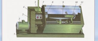
The electrified wood lathe (item 8 in the previous figure) has remained virtually unchanged since the end of the 19th century (see also figure below):
- a – motor rotor and other massive drive parts do not require the use of a separate flywheel;
- b – the clamping chuck can accommodate various tips for different types of workpieces (see below) or a drill;
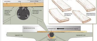
- c – a tool rest with a rotating shelf-support for the cutter, mounted on a movable carriage, makes it possible to carry out a wide variety of working operations;
- d – tailstock with a rotating center allows you to bring the processing accuracy to the maximum possible on wood;
- d – the tailstock quill feed screw (see below) makes it possible to carry out complex processing of a workpiece into a part in one installation. During processing, the wood yields under the pressure of the holder and the center. If the tailstock is fixed rigidly, the workpiece becomes loose during processing. The machine has to be stopped and the blanks reinstalled, which in no way contributes to the quality of the work.
Design and kinematic diagram of a modern wood lathe
What if there is no motor?
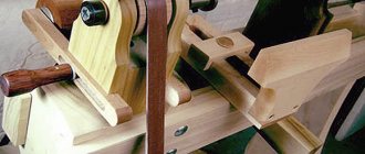
A non-volatile wood lathe can still be useful today; say, at a dacha or an unequipped construction site. The muscular strength of a normally developed person is sufficient to turn pieces of ordinary timber with a diameter of approx. up to 150 mm. In such a case, 2 options are possible (see next figure): a good old machine with a foot drive (the dimensions of its most important unit, the crank, are given at the top right); For more details about it, see below, and processing on trestles with manually driven tow rope (bottom right in the figure). You can’t round timber to the girth in this way, but it is possible to grind the support pillars of a porch, gazebo or canopy over a barbecue.
Construction of energy-independent wood lathes
Make or buy?
The first question that needs to be resolved: since some mandatory costs (see below) are inevitable, is there any opportunity to purchase a machine for wood processing without taking out a loan or cutting the budget? There are some, and they are very good.
Household woodworking machines for industrial production
If you come across the old UBDN-1 (on the left in the figure) or its modern analogues (in the center) at a reasonable price, don’t yawn! There is no need to convert anything at home: the motor is up to 350 W with double insulation of the windings. The machine plugs into a regular outlet; no grounding is required. And you will receive in one product:
- Circular saw;
- Electrojac for sharpening tools, etc.;
- Jointer;
- Disc grinder;
- Horizontal drilling machine;
- Lathe for wood processing.
Another option, most likely cheaper, but only for horizontal drilling and turning - a drill stand that turns it into a lathe, on the right in Fig. Drill bit beds for drills are almost peddled on the streets, but not everyone knows about lathes. Meanwhile, an electric drill as a drive for a wood cutting machine has serious advantages (see below), and a lathe with it will be no worse than a branded one. But much cheaper.
Note: to begin with, it’s better to quickly build a simple lathe and work on it a little. Wood turning skills are easy to develop, and how to quickly make a simple wood lathe, see the video:
Video: a simple homemade lathe
Classification of woodworking machines
Many types of equipment are used in the woodworking industry. The main characteristics by which classification is made are the technological process and design features.
Technological features:
- Cutting;
- Gluing and assembly;
- Presses;
- Finishing;
- Dryers.
Equipment of different designs for performing the same operations may differ in operating technology.
- Processing 1 or many items;
- Number of threads;
- 1-axis or 4-axis;
- By the number of spindles;
- Along the trajectory of movement of the processed material;
- By the nature of the presentation.
- By cyclicality.
Main material
The next question is what to make a homemade lathe from? The answer seems obvious: made of metal, after all, the machine cannot be weaker than the workpiece? How did the primitives drill into stone with wood? How did the ancient Egyptians use wood and copper (there was no bronze yet) to build pyramids? And see above about the main issue of machine tool building.
A lathe for processing wood can be made of metal (pos. 1 in the figure), metal-wood, pos. 2, from scrap materials with minimal use of metal, pos. 3 and even... without a frame, pos. 4. So, on any of them, a sufficiently experienced and careful craftsman can regularly work for a long time with maximum precision for wood. Wood is not only a noble, but also a grateful material.
Homemade wood lathes from various materials
What tree?
Yes, but what kind of wood should I take? The best is oak without defects, seasoned, having undergone complete natural shrinkage and shrinkage. Lathes made of high-quality oak 100 or more years ago are still in operation. As for homemade work, the bed and headstocks of an oak (literally) machine are made very simply, see below.
If there is no oak lumber of suitable quality, then you can get by with ordinary construction pine, but the frame will have to be made according to a frame-beam power structure. In Anglo-Saxon countries, where oaks have long been registered individually, such home lathes are very common. Drawings of an “English” wood lathe with a frame made of ordinary timber are shown in Fig; dimensions in inches. This is actually an ancient foot-operated machine with a crank, adapted for an electric drive. To return it to a non-volatile form, it is enough to extend the middle stand of the frame to the bottom, place it on a paw and mount the pedal with a connecting rod, crank and flywheel, see above.
Drawings of a wood lathe with a frame made of ordinary construction lumber
Drive unit
Working with a muscle motor is, of course, not an acquired taste: now electricity is available almost everywhere. In extreme cases, you can also get power from a car battery through a voltage converter. If you come across something like this somewhere in other articles on this topic: pull a 3-phase cable towards you, make a protective grounding, buy a 3-5 kW motor, do not believe the elephant that he is a buffalo. To round a piece of wood of medium “clumsiness” to a diameter of 300 mm, a machine drive power of 1-1.5 kW is sufficient; for turning 200 mm logs into a figured support post – 350 W.
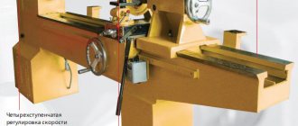
Spindle speed is much more important. Its rotation frequency should not exceed 600-700 rpm, otherwise the likelihood of the cutter “biting” and causing a traumatic situation increases sharply. It is best to limit yourself to speeds set in the range (60-70) - (300-400) 1/min. Then the following are possible. drive options:
- Asynchronous motor with double insulation and capacitor start + mechanical transmission.
- The engine is the same type, 2-4 speed.
- Drive by electric drill.
Just a motor
It’s not easy, because it is impossible to regulate the rotation speed of an asynchronous electric motor by changing the supply voltage: the rotor slip increases like an avalanche and, accordingly. torque decreases. Making a powerful frequency converter is difficult and expensive. All that remains is a 2-3 speed manual transmission. Belt or chain - they dampen jerks due to inhomogeneities of the workpiece, and gear, on the contrary, strengthens them. Plus – heavy rotor, heavy pulleys, elastic belt. The inertia of the torsional drive is such that it is possible to sharpen completely knotty blocks of shape on a cut that has nothing in common with a circle. The downside is that you need to order or look for turned pulleys.
Motor from the washing machine
The rotation speed of an asynchronous electric motor can be changed stepwise by switching the windings. Motors of this type are installed in some models of washing machines (only these are installed in washing machines with direct drum drive) and in floor fans with airflow switching. The rotation speeds in both cases are ideal for wood turning. Motor power from fan approx. 40-70 W, which is enough for a mini-machine (see below). The motor power from the washing machine is 300-400 W – quite enough.
Drawings of a wood lathe with a motor from a washing machine are shown in the figure:
Drawings of a wood lathe with a washing machine motor
The motor from a washing machine with direct drum drive as a drive for a lathe for wood processing has a great advantage: its bearing units are designed for a large unbalanced load, so the most viscous and twisted wood can be turned. But with knots the situation is worse: the flywheel is just a motor rotor, and the cutter will twitch on them.
Note: how to make a wood lathe with a washing machine motor, see video:
Video: lathe with a washing machine engine
From a drill
Dimensions of Morse taper for drill chuck No. 1
From the point of view of an ordinary home craftsman, both machines have a big drawback: on the headstock you need to either install a gripper only for wood, or order an adapter for the motor shaft with a Morse taper for a clamping jaw chuck. Finding the sizes of standard Morse cones on the Internet is not difficult; For the dimensions of the cone for a regular drill chuck No. 1, see Fig. on right. But – you need to sharpen the cone with an accuracy no worse than +/–0.025 mm. That is, you need a metal lathe with increased accuracy of 0.02 mm. There may simply not be a sufficiently qualified master who owns such equipment within reach.
If the machine drive is an electric drill, the problems of precision machining disappear: the chuck can be removed with a homemade puller, and a standard commercial holder for a wooden workpiece can be placed on the cone. Or simply clamp the same one in a chuck, but cheaper with a cylindrical shank. Or even make a workpiece holder yourself (see below).
The design of such an important unit as the headstock in a drill lathe is also extremely simplified: it turns into a simple clamp. Two options for drawings of a clamp for a drill to a lathe are shown in Fig:
Headstocks - clamps for a wood lathe from a drill
On the left is metal; on the right - made of solid fine-grained wood. Wooden is better: it dampens vibrations well and does not damage the collar of the drill. Its production has a certain peculiarities:
- Threaded rod for clamping wing 1 is needed M10-M12;
- The blind hole for the pin is first drilled 1-1.5 m narrower so that it fits into it with a turn along the thread;
- The upper part of the hole is drilled to its full diameter;
- The pin is screwed in until it stops;
- The workpiece is laid flat and a through hole is drilled in place for a locking screw 2 M4-M6;
- Fix the pin with a locking screw;
- The assembly is finally assembled.
An electric drill as a machine drive has only one drawback: a commutator motor with a thyristor speed controller. At low rotation speeds, the torque on the shaft drops noticeably, this can be felt already during drilling. Therefore, using a drill machine with a power of 280-350 W, you can sharpen wooden workpieces with a diameter of approx. up to 150 mm. However, the simplification of the technology for manufacturing a lathe for wood processing driven by a drill is so thorough that machines from a drill are made in a wide variety of options, see the video selection:
From scrap materials without a bed:
Video: wood lathe quickly
With a plywood frame:
Video: plywood lathe with drill motor
Regular design:
Video: universal wood lathe
Improved with expanded functionality:
Video: Improved wood lathe from a drill
bed
Metal and oak wood lathe beds have their advantages and disadvantages. But by combining wooden power (load-bearing) elements with reinforced metal fasteners, it is possible to get a frame that is made “on the knee” with hand tools + an electric drill and will last at least 20-30 years.
The design of the combined bed of a wood lathe is shown in the figure:
Construction of a wood lathe bed made of oak on reinforced metal fasteners
The main structural material is standard oak timber 100x100, 3 m long. Overall length of the frame is 1.2 m. The drawing is to scale, the missing dimensions can be removed and converted into mm from it. If there is more good oak, the length of the frame can be increased to 1.5-2 m. Both headstocks are of the same design and are designed for homemade rotation units, see below. The ridges at the bottom of the headstocks prevent misalignment of the centers. The entire structure can be made with hand carpentry tools and an electric drill.
Note: a mini wood lathe was made using essentially the same power circuit, see next. rice. A motor from a 2-3 speed floor fan, see above, with a 1:1 gear is suitable for it.
If it's still metal
The entire set of qualities of an oak bed is quite sufficient for wood turning. The use of metal for this purpose in mass production is dictated by economic considerations: simply the cost of a metal product intended for continuous 3-shift operation turns out to be much less than a wooden one. 1 cu. m of seasoned oak costs much more than a hundredweight of conventional structural steel.
Amateur craftsmen, without knowing it, often “for the sake of strength” make the beds of wood lathes from channel bars. But it turns out rough even for “wooden” precision (on the left in the figure), and it is not realistic to trim the working surfaces of channels at home. In addition, welding can cause the entire structure to act like a “propeller,” which is completely impossible to correct. Therefore, it is better to assemble a channel frame with bolts (on the right in the figure).
Lathe beds to channel wood
Much more reliable in this regard is a frame made of paired pipes (on the left in the next figure): when welding it moves less, the misalignment can be corrected by tightening the frame with bolts to the base, and it is possible to achieve a divergence of the centers of handmade headstocks of 0.2 mm or less . Drawings of a welded tubular bed of a wood lathe from a drill are also shown in Fig.
Drawings of a wood lathe with a metal frame made of double pipes
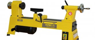
What cheap used machines can you find?
BELMASH WL-300/450. Made for mechanical processing of wood. Cast iron bed. Smooth rotation allows for high-quality grinding of parts. The small diameter of the workpiece is 30.5 cm, the clearance between centers is 45.5 cm, which provides a good opportunity to work productively on the machine without fatigue or fatigue.
The machine has 5 speeds. Changing the speed is done by shifting the drive belt to another pulley stage. A convenient arrangement of machine tools is created by the console. Rotation speed can be easily changed.
Grandmas
It would seem that it is impossible to make the headstocks of a lathe, and the back one with a rotating center, without precision turning operations. No, it’s possible – using the phenomenon of an oil hydrodynamic cushion (OHB). This, by the way, is one of the ways to answer the question: how to make parts for a machine with an accuracy of 0.2 on a machine with an accuracy of 1. In mechanical engineering, HDP is rarely used, because for its formation and stabilization, the machine with the workpiece fixed in it must run at idle for 2-5 minutes. If a shift lesson consists of only 10 parts, then the daily loss of working time will be up to an hour or half an hour, which is “off scale” in mass production. But in general, HDP is not uncommon in technology. For example, warming up the internal combustion engine of your car is necessary, incl. and in order for the GDS to form between the connecting rod clamps and the crankshaft journals, otherwise the engine life is sharply reduced.
What is GDP
The principle of operation of the HDP is shown in the figure:
Operating principle of a hydrodynamic oil cushion
Any grease is suitable for it: grease, grease, cyatim, fiol. But the best thing is shahtol, a special lubricant for mining machines and mechanisms. Due to difficult working conditions, they, like the Kalashnikov assault rifle, are made with large gaps between the rubbing parts, but they are not required to have a high rate of fire. Shakhtol is specially designed for relatively slow movable rotation joints and is perfectly suited for the headstocks of a wood lathe using a GDP.
Headstock
The design of a typical headstock of a woodworking lathe is shown on the left in Fig. There are already a lot of metal lathes in it for the amateur, and the shaft journals and bearing cap seats need to be sharpened with the same precision as a Morse taper.
Design of standard and homemade headstocks of a wood lathe
For a homemade headstock using the HDP, you will need, in addition to purchased threaded parts: M12-M20 studs for the shaft, nuts and washers for them, another piece of bronze (not brass!) foil 0.2-0.35 mm thick and, for the holder, a steel tube with walls of sufficient thickness (see right in the figure). The entire assembly assembly is made. way:
- The tube on the holder is cut exactly to size according to the thickness of the headstock's wooden body, and pressed into it;
- The body with the holder is laid flat, laid flat and the tube is drilled out along the diameter of the threaded shaft;
- The inner corners of the cage holes are smoothed by hand scraping - a reamer - as is done when installing air conditioners;
- A rectangle is cut out of bronze foil with a height equal to the thickness of the headstock body and a width of 3 shaft diameters (for M12 36 mm, for M16 48 mm), its corners are slightly cut at 45 degrees. 3 diameters, because the bronze liner should barely meet at the edges, and π=3.1415926...
- From the same foil, using a ballerina compass with two needles, cut out 6-8 bronze washers;
- The washers are pressed one by one with your palms between plywood with fine sandpaper glued to them and, turning your hands back and forth, the burrs are removed;
- The shaft is wrapped in the same sandpaper and, squeezing it with your hand, the shaft is pulled through several times with a twist to slightly remove the sharp edges of the thread;
- Wrap the shaft in foil and try to insert it dry into the holder. If necessary, repeat operation 7. It is necessary that the shaft in the foil wrapper fits tightly and is difficult to rotate in the cage by hand;
- Take out the shaft, remove the foil and screw one of the nuts onto it until it fits;
- Coat the shaft threads generously with grease;
- The same grease is used to lubricate the inside of the cage;
- Place a regular steel and 3-4 bronze washers on one side, generously lubricating each one with the same lubricant;
- Wrap the shaft in foil again and insert it into the cage;
- Place the washers on the other side in reverse order, also lubricating them generously;
- Screw and tighten the other nut so tightly that the shaft can barely be turned by hand;
- The nuts are temporarily secured with locknuts;
- Lay the workpiece flat and drill through holes for the cotter pins;
- The standard nuts are tightened. It is best to cut bicycle spokes, they have very high shear strength;
- They assemble the headstock, put its pulley in place;
- Turn the pulley by hand until it rotates tightly, but without jamming;
- Assemble the machine drive and start it idling at minimum spindle speed (in the slowest gear) until the motor reaches full speed. If necessary, push the pulley with your hand;
- Repeat step 21 at maximum spindle speed (in the fastest gear);
- Place the workpiece gripper in place - the unit is ready for work.
If you don’t trust all sorts of very clever physics (although units with HDF maintain accuracy no worse than their rolling friction counterparts), then in Fig. - drawings of a bearing assembly, equally suitable for a homemade circular saw and a wood lathe. In the latter case, a flat sole with side supports is not needed - the round body is simply inserted into the headstock body and secured with a screw. Instead of a saw blade, use either a faceplate or an adapter with a cone for a clamping chuck (part 6).
Drawings of a bearing assembly for a circular saw or the headstock of a wood lathe
Tailstock
Designs of rotating centers of the tailstock of lathes for metal and wood
The designs of the rotating centers of lathes for metal (above in the figure on the right) and for wood (at the bottom) are not fundamentally different, only the “wooden” one is designed for many times lower loads. But in work, especially at home, there is a significant difference: axial holes in turned wooden parts are drilled extremely rarely, because This greatly reduces their strength - wood, unlike metal, cracks easily. That is, by abandoning the quill for replaceable working parts, it is possible to simplify the design of the tailstock until it is suitable for manufacturing “on the knee” with a small proportion of simple custom-made turning work.
A typical tailstock design for a wood lathe is shown in Fig. below. On the right there is an insert with a rotating center in the wooden tailstock, made from a garage door hinge. The HDP is also used here, and the center shank is adjusted to the holder in the same way as the headstock shaft, but simpler and lighter: the gap between the pin and the socket of the garage hinge is approx. 0.5 mm and, as a rule, the unit turns out to be suitable for operation without adjustment and grinding.
Standard tailstock of a wood lathe and a homemade insert for it from a garage hinge
Some difficulties are caused only by fixing the center from the reverse longitudinal stroke. It is unrealistic to cut a trapezoidal thread and make a locking block or eccentric for it at home, and a locking screw will quickly crush a regular metric thread. The output is a floating aluminum bushing. Mechanics are familiar with this method: if you need to clamp a threaded part in a vice, they wrap it in thin aluminum or place it between aluminum spacers - absolutely nothing happens to the thread.
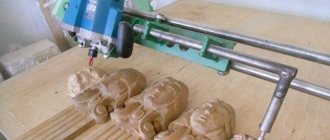
Wood lathe with copier
The scheme of operation on a turning and copying machine is as follows:
- At the top of the frame, a stencil made of wood is installed on special fasteners - a copier.
- The rolling roller moves along the outside of the copier.
- By connecting the roller to the cutting tool using a rigid fastening method, the cutter accurately transfers the movement of the roller along the copier to the wood. Where there is a recess on the copier, there will be a convex element on the wood, and the protrusion on the stencil will appear as a notch in the finished wooden object.
For the production of identical elements of wooden decor, a machine with a copier is the most convenient solution.
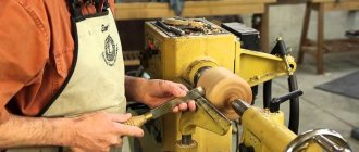
A lathe, on which processing is carried out using hand tools: rayer, meisel, scraper, is not particularly accurate. When making several similar parts from wood with the same density characteristics, you have to rely only on the skill of the turner and his eye, but it is still very difficult to give a 100% guarantee that they will be identical. The use of different types of wood in the production means that cutters and devices will need to be different from each other.
The wood turning and copying machine is distinguished by the accuracy of reproduction of the stored data. The copier is a kind of CNC prototype. One copier allows you to make identical things an infinite number of times, which is necessary for the manufacture of balusters for railings or legs for cabinet furniture sets. In workshops where production is on stream, it is more advisable to use CNC-equipped copying machines.
When working with wood, there is always a manual process of bringing the part to perfection using sandpaper. Grinding is carried out at the stage while the object is secured between the lathe heads. Rotation is programmed at lower speeds than those at which cutting was performed.
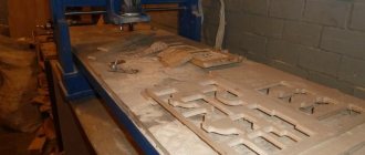
Lathes are used to turn oblong-shaped wooden elements. The workpiece is mounted on a spindle with approximately equal weight distribution. To do this, holes are drilled in the center of the end ends of the wooden workpiece - this is necessary so that the rotation of the shaft is uniform. Most often, cylindrical wood or timber with planed corners are used. Cutting is carried out not only on the external, but also on the internal surface of the workpiece. The shapes of finished products can be complex, conical, cylindrical - symmetrical relative to the center of the product.
A desktop wood lathe equipped with a computer programming system has high precision in reproducing complex designs. It can be used to create very complex carving elements.
[Show slideshow]
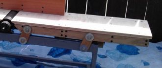
Podruchnik
Drawings of a tool rest for a homemade wood lathe
The simplest tool for a chisel is a piece of board with a wooden boss nailed/screwed to it. But this is not suitable for fine work: when sharpening shaped parts, you need to rotate the shelf (stop) of the cutter without loosening the fastening of the tool rest itself and without displacing it. Therefore, the tool rest needs to be made of metal with a rotary stop, but custom turning and milling work is not required for this; for drawings see fig. on right.
Types of woodworking machines
Today, there are three main types of turning units for processing wooden workpieces, depending on their purpose:
- industrial (for large enterprises);
- semi-professional (for small enterprises);
- tabletop (for home use).
For organizing small production, semi-professional machines are suitable, characterized by high productivity and not large sizes.
Devices of the first type are characterized by high productivity, so they are used for mass production of various products. From a functional point of view, they have no equal, as they are able to perform a large amount of work of various kinds in a minimum amount of time. The mass of such devices is at least 200 kg, and the minimum power rating is 1 kW.
Semi-professional machines used for small industries are characterized by smaller dimensions and, accordingly, weight. Their weight ranges from 40 to 90 kg, and their functionality is significantly less than that of industrial devices, but it is quite enough to meet the needs of a small workshop. The power indicator of such units varies from 0.5 to 1 kW.
Desktop devices are used exclusively for domestic purposes. As a rule, such a device is installed on a workbench or any other work surface and is used for processing single wooden parts. The weight of a mini wood lathe does not exceed 20-40 kg, and the power indicator is always below 0.5 kW.
Note! To select a turning device, you must first take into account its purpose, as well as the availability of individual functions.
When choosing a lathe model, you should understand what tasks will need to be implemented
Today you can find many types of turning devices for wood processing that are used at home. They differ in their functionality, as well as a number of other characteristics. Let's look at the most popular devices used by home craftsmen for processing wood blanks:
- milling;
- screw;
- copy-milling;
- thicknesser;
- CNC devices.
Wood turning and milling machines are used, as a rule, for boring grooves. Screw units are used to apply threads to workpieces and produce cone-shaped parts. Machines equipped with a copier allow you to produce products of unusual shapes and perform work much faster and more accurately.
Copiers use special stencils. Thicknessing machines allow you to plan a board. CNC wood lathes are automatic units that operate according to a given program.
There are several types of woodworking machines on the market, differing in their functionality and characteristics.
Holder
So we come to the last question: how to securely secure the workpiece in the headstock of a woodworking lathe? Considering that wood easily tears, crumples, and chips, and the wood that is turned into a lathe sometimes comes in simply amazing shapes.
The answer to this question is not as scary as the devil paints it. Universal holder – trident, pos. 1 in Fig. This is exactly what household woodworking machines are equipped with, for example. the mentioned UBDN-1. The shank is either smooth for a clamping chuck, or threaded for installation on the shaft. The trident holder reliably holds workpieces up to 100-120 mm in diameter, and round ones – up to 200 mm. There is only one drawback: it is very difficult to make a good trident for a wood lathe.
Workpiece holders for wood lathe
Screw chuck for small clean work (e.g. turning wooden glasses), pos. 2, it is generally impossible to do without special equipment, but it is successfully replaced by a clamping chuck, pos. 3. If, on the contrary, you need to process a large workpiece with an irregular configuration in the cut, use a faceplate, pos. 4.
A faceplate for turning wood can also be made independently from bakelized plywood with a thickness of 12-16 mm. In this case, the washer is made of 2 layers: the same one made of sheet steel 1-1.5 mm thick is attached to the plywood circle on the back side. The holes for the tenons in the plywood circle are drilled through, and instead of the turned tenons, you can then install the cut off points of the nails. The glass for installing the faceplate under the nut on the threaded shaft shank can also be assembled from plywood rings and a steel bottom.
Finally, based on a 3-4-layer faceplate, you can make a homemade wood-look jaw chuck, pos. 5. Are your fists definitely not going to meet? So the accuracy of the workpiece is even worse. But you can sharpen bowls, saucers, etc. from slices of valuable wood. products on which there will be no traces of processing.
Note: the variety of holders for wooden workpieces is not limited to those described. For example, see the video on how to make a mini lathe with a crown holder for the smallest woodworking:
Video: mini wood lathe
What factors influence the cost and main selection criteria?
The cost is influenced by the factors of using machines for their intended purpose, dimensions, the presence of software devices, the number of rotational speeds of the engine and drive system. The brand of a turning machine increases its cost by 1.3-1.6 times. Important, equipment.
The device, just like a machine, is equipped with a variety of devices for comfort and good control. You need to choose wisely for complete sets at an affordable price. An equipped machine may not produce what you want for work:
- It is better to have a collapsible bed, up to 5-6 mm thick. No longer required. - the basis of a milling machine.
- The engine, economical and not expensive, also helps process wood workpieces well.
- Drivers are selected for the engine and are supplied with it.