Design of the headstock of the STD-120M lathe
The headstock of the STD-120M lathe is used to install and fasten the workpiece and transmit rotational motion to it.
The headstock consists of a shaped body cast from cast iron. It has two coaxially bored holes for radial spherical bearings.
The spindle is a steel shaped shaft, on the right end of which a thread is cut for screwing on a chuck, faceplate and other special devices for securing workpieces.
At the left end of the spindle there is a two-stage drive pulley, which receives movement through a V-belt transmission from an electric motor. Covers with felt padding are attached to the headstock on both sides.
To start and stop the spindle of the STD-120M machine, a control post is placed on the headstock body, and a lamp is located on top.
V-belt transmission. A two-stage pulley is rigidly attached to the electric motor shaft of the STD-120m lathe, which, using a V-belt, transmits rotation to a two-stage pulley mounted on the spindle of the STD-120 machine. By moving the belt from one stage to another, you can change the spindle speed. The V-belt drive of the STD-120m machine is covered by a metal fence, the opening cover of which is interlocked through a limit switch with an electric motor. When it opens, the electric motor is switched off and the spindle of the STD-120m machine stops.
A two-stage pulley is rigidly fixed to the electric motor shaft, which, using a V-belt, transmits rotation to a two-stage pulley mounted on the machine spindle. The V-belt drive is closed by a metal fence, the opening cover of which is interlocked through a limit switch with an electric motor so that when it is opened, the electric motor is switched off and the machine stops. The guard cover is locked with a screw.
Sunday, March 12, 2021
How to make a chuck for a wood lathe
Today I will continue the topic of a homemade lathe and accessories for it.
I haven't made a video on this topic for a long time. And now, while the video is still being prepared, I decided to write this article.
I already raised the topic of the chuck in this article: Homemade lathe chuck.
There are 2 wood lathes in use in my workshop and another one in the making.
I talked about the big machine in one of the old videos:
–
– And I already spoke in detail about the second (desktop) in this video: –
–
I made quite a lot of equipment for both machines. These include faceplates, various types of tridents and drive couplings,
and even a flange with a three-jaw chuck Ф 80 mm. But on a small machine I rarely use a chuck
due to its
large inertia and mass
.
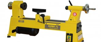
The machine has a fairly high speed - 2700 rpm (for simplicity of design, a direct drive is used - the engine serves as the headstock).
After all, this cartridge has a lot of advantages:
First of all, it allows you to process the end of a part - drill, trim, and bore holes
.
Secondly, the part in such a cartridge is fixed quite firmly.
Thirdly, it is safer than various types of homemade products that fix the workpiece with bolts:
The advantage of a threaded chuck is a more reliable fixation of the workpiece, since it is screwed into the chuck and securely fixed using a thread.
But such a cartridge also has a downside - the difficulty of removing the remainder of the workpiece, which needs to be unscrewed
, and not knock it out.
This process can be simplified by drilling 2 holes in the remainder and using a wrench that is used to clamp the nut securing the cutting disc to the angle grinder.
Video about a homemade cartridge: =
=
I made this cartridge before and, based on operating experience, decided to make another, larger one, without threads.
=
=
For a larger cartridge, I used a water pipe with an outer diameter of F 48 (1 1/2″)
The inner surface of the chuck is cylindrical, with a small “entry” cone, which allows the workpiece to be hammered more tightly
.
There are two holes in the side wall of the chuck, diameter 4 mm, into which, if necessary, you can screw screws for better fixation of the workpiece.
There are also holes Ф 10 mm to control the depth (position) of the workpiece
To make these cartridges, I used a metal lathe (TV-4) and a welding machine.
But there is another way that does not require complex equipment.
Design of a faceplate for a wood lathe
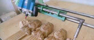
Design and operating principle of a CNC lathe
A faceplate for a wood lathe is a part in the shape of a steel disk with holes for fastening a dimensional workpiece. There are many types of faceplates, differing from each other:
- material of manufacture;
- disk thickness;
- size and configuration of mounting holes;
- manufacturing method;
- heat treatment;
- availability of additional accessories.
Turning is often encountered when working with concave planes of workpieces; the processed parts have a large cross-section and thickness. It is problematic to secure such materials on other machines; the bending makes it difficult to grasp the necessary part of the workpiece.
A faceplate is a cast metal disk that has a threaded center hole for attaching to the spindle of a wood lathe. The workpiece is secured in the faceplate with metal screws. They pass right through its holes and are securely screwed into the wood.
When sold, a woodworking lathe is equipped with a faceplate with an outer diameter of 100–150 mm. Additionally, specialists can purchase similar products of any size, with a different arrangement of mounting holes and working thickness.
When purchasing for home use, you must choose a faceplate with the maximum outer diameter. It must correspond to the basic size of the bottom of the workpiece being processed.
Prerequisites for using faceplates
When turning wooden products, situations often arise when the turner is required to perform jewelry processing of the edges; the accuracy of such manipulations is impossible to perform on a standard unit. Especially if the part has large dimensions and uneven corners. The workpiece is fixed to the faceplate using hooks.
The blank used for turning the bowl must be secured very carefully, otherwise the part will break from its place of fixation and the work will be ruined.
There is a high risk of serious consequences and accidents if a heavy workpiece falls off the machine spindle. Many professional wood turners make special fastening devices with their own hands.
The dimensions of the unit itself are small; it can fit in a small workshop or garage of a private house. There is no need to provide forced ventilation in the room where the equipment will be operated. Many craftsmen install the machine between two windows, this allows for increased natural ventilation.
Faceplate at home
To assemble the unit at home, the master must know the work schedule; this will simplify the installation of all parts and allow the machine to be used for a long time. The technique is quite simple, but all points require specialist attention and dexterity. Step-by-step instructions for making a homemade faceplate:
- Take a flat steel sheet 10 mm thick.
- Steel, undamaged corner 50x50 mm, M8x30 bolts in the amount of 8 pieces, flat washers and nuts for them.
- Carefully consider how a homemade faceplate for a wood lathe will be attached to the spindle of the unit. Buy or machine a threaded bushing.
- Mark the steel plate with a circle of the required diameter. Draw two axes so that they pass through the center and intersect at an angle of 90º.
- Using a jigsaw, make a circle along the marked line and carefully sand it.
- Wet the through grooves along the central axes, not reaching 3 cm from the border of the part, moving a few centimeters away from the center. It is better to pre-drill holes of a slightly larger cross-section than the prepared bolts.
- Saw off four identical segments from a solid corner. Drill one flange of each segment with the same drill as the plate.
- Cut M8 threads in the other two corner flanges. Screw the bolts into it.
- Weld a threaded bushing for fastening to the shaft to the plate.
- Screw the corners through the washers to the faceplate using bolts.
- I made my own faceplate for a lathe. It is necessary to attach it to the spindle of the unit and begin work.
Attach the faceplates to the spindle
To fix the workpieces with such a washer, the corners are moved to the required position and secured with nuts. Each part is securely clamped using bolts; they are screwed into the shelves with an angle bracket with an M8 thread.
video instructions for making it yourself, how to make a cartridge, faceplate, photo and price
All photos from the article
There are many versions of lathes that can be used to process wood pieces. They can be very tiny, in which a conventional electric drill is used as a motor, and quite powerful with large power plants and equipment elements.
In our case, we will use materials, the main ones of which can be found in the garage or basement, and the missing ones can be easily purchased at the construction market or in a store.
In the photo - a 3 in 1 wood lathe
Most of us will most likely doubt our abilities and will not even try to repeat what was proposed. At the same time, everything written below will not pose any particular difficulties for those who have ever worked with wood. You won’t see any special methods or techniques here, everything is as simple and accessible as possible.
Materials and equipment
Before you learn how to make a wood lathe yourself, you need to prepare for work.
In this case you will need:
- plywood 18 mm thick, from which basically all parts will be made;
- 50 mm thick boards for making the headstock;
- timber with a section of 50x50 mm for the frame.
Equipment you should prepare:
- The electric motor is 220V or 380V, depending on what voltage is suitable for your workshop.
- Pulley - it is better to take a 3-way pulley, with which you can adjust the optimal processing speed. It is advisable to purchase a joint pair.
- V-belt.
- Drill chuck - used as the main holder on the headstock. This is a kind of homemade chuck for a wood lathe.
- An electrical box with a switch and protection against unauthorized operation.
- Wood screws of various sizes.
- Bolts, washers, butterfly nuts and T-nuts.
- Plastic protective cover.
- Steel plate.
- Mounting rail for moving the tailstock along the frame - if the price does not suit you, you can replace it with an aluminum cornice.
- Screw rod – regulates the reliability of fixing the workpiece in the centers of the machine.
- The union nut is a stopper on the headstock.
- Metal loops – allow for optimal belt tension on the pulleys thanks to the console.
- Retaining rings are used to hold bearings in their seats.
A homemade faceplate for a wood lathe is used instead of a lathe chuck
Below are step-by-step instructions for the process.
Manufacturing of the bed
The element has important functional significance and is a solid foundation for the remaining moving parts of our machine.
- The “bed” is made of 2 sheets of plywood, which are connected to each other using glue and self-tapping screws:
- the first has a size of 18x500x1200 mm;
- the second – 25x500x1200 mm.
“Bed” of the future wood lathe
- Measure two 1200 mm long sections on the timber and saw them off.
- Install on the “bed” with a pitch of 50 mm between each other.
- In each block in the middle, make grooves for guides 900 mm long for installing headstocks and install them.
Tip: instead of standard T-shaped guides, you can use used aluminum curtain rods, they work just as well.
Machine engine
In this step, everything will depend on what equipment you can buy or find in your home. We will use a motor from a grinding machine, but it is better if you can get a motor with a low speed of 1750 rpm.
Therefore, in our case, we will have to reduce the declared speed of 3000 rpm using sets of pulleys, for which it is better to use two sets - for the motor and the headstock of the machine.
A set of pulleys of different diameters allows you to adjust the speed of rotation of the wooden workpiece
It is enough to purchase 3-step pulleys that will help you set the speed from 700 rpm to more than 4000 rpm on the workpiece. Here's some sample data:
| Pulley on the engine | Pulley on the headstock | Workpiece rotation speed |
| small | big | 700 |
| small | average | 1000 |
| average | big | 1250 |
| big | big | 1725 |
| big | average | 2500 |
| average | small | 3000 |
| big | small | 4150 |
The motor is mounted on a plywood platform, which hangs freely, which creates the necessary belt tension
Advice: before purchasing, we recommend asking the seller about the possibilities of simultaneous operation of the engine with installed pulleys.
The platform for the engine will be plywood, which is attached to the main frame with hinges. Please note that each of them must be located 60 mm from the edge for secure fastening.
Do-it-yourself homemade wood lathes usually use a belt drive, and you need to move the belts on the pulleys yourself
For easy access to starting and stopping the machine, install an on/off button on the front of the lathe. The connection is not difficult - you should insert it into the circuit between the engine and the 220/380 V network.
Protect the button with the top cover from unauthorized start of the equipment
Headstock
The element transmits rotation to the workpiece from the engine and reliably holds equipment parts, so it must be powerful enough. Basically, the size of the headstock depends on the diameter of the pulley. It can be made from hardwood or using a sandwich of plywood sheets, which will be no less reliable.
The headstock should be as reliable as possible
In our version, we used 2 T-shaped blanks made of solid wood with a thickness of 150 mm and a height of 165 mm. We connected them together with a third workpiece of the tongue-and-groove type. The depth of the structure must correspond to the normal rotation of the largest diameter pulley.
Tip: you can make 3 parts of the headstock from plywood.
All elements of the headstock must be securely screwed
Its mechanism consists of two mandrels with bearings and retaining rings. Each of them is screwed with self-tapping screws to the headstock on both sides.
Tailstock
To make it, take a ready-made sandwich from glued sheets of plywood.
T-shaped blanks have the following overall dimensions:
- width – 150 mm;
- height – 215 mm.
Tailstock bevel angles don't matter, let them be 25˚
A hole should be made in the center at the top, which should be level with the headstock chuck. To securely fix the workpiece in the centers, a screw rod 180 mm long is used.
The tailstock is attached to the bed using butterfly nuts.
A lock nut is also used inside between the tailstock parts to limit the extension of the rod.
The locking nut allows you to adjust the extension of the screw rod
Inside, between the parts of the tailstock, it is necessary to insert additional elements made of wood, which will increase its reliability. To move the screw rod from the outside, we recommend making a flywheel from interconnected pieces of plywood.
A plywood flywheel will make it easier to adjust the clamping of the workpiece on the machine
Belt and whetstone guard
We hope that you have not forgotten how important safety precautions are when working with rotating elements. In our case, we should install a protective cover on the belt and the second part of the grinding mill, so that neither one nor the other can harm us in the event of a rupture or breakage.
Make a protective cover for the drive belt and whetstone
In the first case, you can purchase it in a store or make a plastic casing yourself, securing it on both sides with two bolts and nuts. Its dimensions, for example, can be as follows - 450x170x270 mm. The main thing is that it does not interfere, but only protects the worker.
In the second case, you can use an old plastic bucket of a suitable diameter, which must be secured above the sanding wheel. It will spin constantly, so this protection will never be superfluous.
Caliper
To make it, take 18 mm plywood:
- Make the base of the element from a wooden block measuring 100 by 300 mm. Then make a groove in it for free movement of bolts with butterfly nuts, which can securely hold the caliper in the desired position.
Ready caliper on the bed
- The second part is intended for installation on the base of the caliper and is rotary. The block has rounded corners and two holes for lower and upper fastening.
Mounting the caliper on the frame
- The third part holds the swing arm.
- The fourth element is the main block for holding the support arm. Its sides should be cut at an angle of 45˚ for greater reliability. Can be replaced with metal.
The caliper consists of 6 elements
- The most important element is the support arm, which must be glued and screwed to the lower base as securely as possible. Its size is 100 by 200 mm, the bend of the sides ends at a distance of 30 mm to its top, which is beveled at an angle of 30˚.
- A metal plate installed with 4 self-tapping screws on the top will reduce wear on the element.
With the support of the support, you can process the workpiece on the machine
Tip: Before using the support, check that the tool can slide easily on the plate.
Conclusion
Today you learned how to make a wood lathe, which made maximum use of wood as the main material - plywood, timber and board. It is quite possible to make this design at home yourself, for which you will need to purchase or use an electric motor with transmission pulleys.
While working, you must remember to follow safety rules and safety glasses. The video in this article will give you the opportunity to find additional information on the above topic.
rubankom.com
Lanyard selection
Technical characteristics of the desktop lathe 1d601
Selecting a tool based on the expected load is a guarantee that it will not deform during operation. The tables that the seller has will help you do this, where the manufacturer indicates which model is designed for what. But the choice depends not only on the weight of the cargo, but also on the function
The first parameter you need to pay attention to is the thread diameter. Screw fastening for M10, M8, M12, M20, M16, have different threads
The number following the letter “M” indicates the thread diameter in millimeters, M12 is a 12 mm thread. Marking T 10-01, T 30-01 indicates the load at which the part begins to collapse.
Lanyards are most often used when working outdoors, where they are exposed to moisture and temperature changes. Modern parts are not supplied without protection from such exposure; most often this is galvanizing.
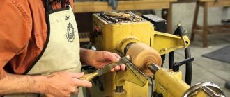
First experience of turning on a wood lathe with a faceplate. DIY wooden turning souvenir
Design and purpose of the tailstock of a metal lathe
———————————————————————————————————— This is a channel about carpentry - how to make wood with your own hands.
Watch my other videos:
***Carpentry projects (furniture, etc.)*** https://www.youtube.com/watch?v=tejxqO6QJx4&list=PLh72fBFaYWSiCbtKBCOakP5z2x3B9pVYA
***Tools and workshop*** https://www.youtube.com/watch?v=23-rRozXLLo&list=PLh72fBFaYWSiQ7axgYGNVDbl22WAX3UAv
***Useful carpentry tricks*** https://www.youtube.com/watch?v=p1TQGf1qXQo&list=PLh72fBFaYWSjwM9P97tIYl2WDcc_9CVKc
***Turning projects***
https://youtube.com/watch?v=v%2520
***Carpenter's thoughts (reflections, analytics)*** https://www.youtube.com/watch?v=rk4hX12gfXM&list=PLh72fBFaYWShdQCFHYPwRImDjTlm0Y5OJ
General description and design
The typical faceplate design is the same for metal and wood machines. In general, it is a disk on which workpiece fastening units are made. The material used for manufacturing is cast iron or steel. Other materials are used less frequently.
The equipment is attached to the spindle using threaded holes or conical hubs. Their parameters are selected for the specific dimensions of the output end of the shaft. If the fixture is equipped with a cylindrical hub, it is clamped directly into the machine chuck.
The workpiece is secured using clamps, crutches, clamps or other clamping devices. Often a lathe chuck is used for this purpose. It can be mounted on the faceplate along the axis of rotation or offset.
When using faceplates, increased attention is paid to work safety. Large dimensions, non-standard fastenings, and non-cylindrical shape of the surfaces being processed pose an increased danger to the turner and others. Before starting work, all structural elements of the equipment should be secured and balanced in order to avoid destruction of the structure and scattering of individual components.
Additional accessories
When turning thin-walled products or working with fragile wood, metal fastening rings are used. Having the skill of handling metal, you can make them yourself. Also, in pairs with type C jaws, screw inserts can be used, screwed into a hole pre-drilled in the part. Chucks designed to solve specific problems in wood:
- cam with independent adjustment - for eccentric turning;
- collet - clamps round workpieces when tightening the petals of a conical collet with a coupling nut. Has a small capture range;
- cylindrical - a tube with three or more threaded clamps around the circumference; vice - for gripping rectangular workpieces. The parallel jaws are compressed by a screw;
- vacuum – for finishing. It works due to the difference in air pressure created by the pump;
- drilling – for fixing drills. Attached to the tailstock quill.
Set of driving cartridges MK2
Lever view
Perhaps the most popular design. The action of the mechanism is based on the movement of cams and clamps due to the mobility of a two-arm lever. The presence of a hydraulic drive allows you to optimize the design.
The main characteristics of the device include the number of clamps for securing the cam and the ability to move along the working disk. Setting up such a cartridge is quite difficult, especially with non-standard processing.
Changeover occurs according to two schemes:
- Independent adjustment of the cams is a labor-intensive operation and is not performed for every design type of chuck.
- Synchronous movement of cams with a key.
To carry out adjustment, a special key is installed in the groove for adjusting the hydraulic drive.
When working with a device of this type, there is a slight play of the part when rotating. For this reason, lever designs are more often used in roughing.
General concepts about lathe chucks
Lathe chucks are selected depending on the technical characteristics of the device and the spindle, in particular. They represent the main components of the equipment. The mechanism is a cam effect. Dimensions are selected depending on the parameters of the unique workpiece.
The cams ensure reliable fixation of the mechanism. Due to the action of mechanical force, which determines the tightness of the fastening, installation and fastening occurs. The workpiece is fixed using a chuck.
A low-quality cartridge will not hold as tightly as possible; as a result of strong mechanical movement, it can fly off, and the workpiece with it. The chuck ensures smooth movement of the fastener, while the workpiece will not move relative to the center. In the simplest sense of the word, a chuck is a mechanism that is responsible for rotating the workpiece, making its processing efficient and smooth.
Types of faceplates
The simplicity of the faceplate design and wide range of use have given rise to a large number of ways to secure workpieces. However, the device is not completely universal. Different situations may require several different modifications.
Faceplate with T-slots
On the surface of such equipment there are T-shaped grooves, similar to those used on tables of milling machines. Special stops or fastening nuts are inserted into these grooves. The workpiece is pressed to the plane using screws. The design of the device allows you to fasten almost any product. The arrangement of grooves on the surface of the disk is usually orthogonal. Depending on the purpose, the number and frequency of grooves may vary.
Faceplate with through grooves
This type is distinguished by the presence of grooves milled through the part. The workpiece is secured by installing screw clamps. In some cases, the part is simply screwed on from the reverse side. Grooves are most often located along a radius. There are also modifications with ring-type through grooves.
In most cases, grooved faceplates are used for metal lathes. Other turning devices can be easily installed on their surface.
Faceplate with holes
The working surface of the disk of this device has a number of holes located according to the dimensions of the workpiece being fixed. The central hole is threaded, necessary for direct fastening to the spindle shaft. The presence of threads in the mounting holes allows for fastening with standard screws. In other situations, the clamp is performed similarly to the previous option. When using a similar faceplate for a wood lathe, the future part is secured through the holes with ordinary self-tapping screws.
Drive faceplates
When installing a workpiece between two centers, it is necessary to ensure the transmission of torque from the spindle shaft to the workpiece. For this purpose, leash tools are used. Structurally, they are a disk with a slot or hub on the edge. A clamp is put on the part, interacting with the hub, and thereby ensuring rotation of the product.
Faceplates with squares
When processing products with low rigidity, modifications with squares have been used. The workpiece in such devices is mounted on a separate flat or prismatic base. The base itself is made in the form of an angle, the second edge of which is attached to the surface of the washer. In order to maintain the integrity of the workpiece, its fastening is provided at several points over a large area.
Universal and special faceplates
Universal options are suitable for performing a large number of operations and are a combination of several previous modifications. They are based on a base washer, to which replaceable devices are attached - squares, cams, centers and other elements.
Despite its versatility, standard equipment is not always able to provide reliable fastening of unique parts of complex shapes. In this case, the design and manufacture of special machine tools is carried out. The faceplate drawing can be very complex. Another version of special devices, on the contrary, is involved in mass production. To fasten a part of the same type, there is no point in using universal machine tooling. A device designed for a specific task is quite sufficient. To increase overall performance, such a faceplate can be equipped with additional fastening and centering devices.
Requirements for lanyard parts
GOST 9690-71 provides the following options for the design of turnbuckle couplings:
- Stamped closed couplings.
- Stamped open couplings.
- Cast couplings.
- Welded closed couplings.
- Welded open couplings.
In closed-type turnbuckles, the threaded part of the load element is completely located in the coupling body. This is considered safer, because if the gripping device suddenly breaks (which most often happens along the thread), its remains do not fly apart. Therefore, the maximum permissible tension force for closed lanyards is always greater than for open ones.
Read also: Types of bearings and their purpose photo
The manufacturing technology of the couplings also largely determines the capabilities of the lanyard. Thus, stamped couplings (the blanks for which are high-quality structural steel according to GOST 1050, steel grade 20 and higher) are strong and reliable. This is explained by the fact that the macrostructure of stamped products does not have cut fibers, and, therefore, there are no stress concentrators. The same is typical for cast couplings, however, the structure of the cast metal is coarser-grained, therefore, other things being equal, the body of a cast coupling will break faster than a stamped one.
Welded couplings have the worst load-bearing capacity: in the weld zone, the strength of the metal is reduced by 20...25% (for the same reason, it is strictly forbidden to restore damaged lanyards by welding).
The standard allows two designs of round turnbuckles: with a through hole in the middle of the body, and without it. In the first case, the conditions for rotation of the housing when tightening are improved, but the cross-section of the coupling is weakened. The starting material for such couplings is seamless steel pipes in accordance with GOST 8734 made of steel 25 (in low-critical turnbuckles, duralumin and ordinary quality steel St. 3 in accordance with GOST 380 can also be used).
For the compactness of coupling lanyards, the diameter of the cargo grips is important. In closed couplings it does not exceed M42, otherwise the coupling becomes heavy and difficult to adjust. Open type couplings do not have such restrictions.
Turnbuckle couplings are manufactured for the following types of grips:
- BB (fork-fork).
- VU (fork-ring).
- UU (ring-ring).
- GG (hook-hook).
- VG (fork-hook).
- GU (hook-ring).
Download price list
Lanyards are high quality rigging products. The presented types differ in design features, dimensions, weight, and workload. The fork-fork modification provides the highest degree of reliability of lifting equipment. The remaining types are used only in everyday life.
The practical use of lanyards largely depends on their design. The maximum level of reliability of guy ropes and other elements of cargo equipment is ensured by the “fork-fork” design. For non-essential operations and household needs, ring-to-ring, hook-to-ring or hook-to-hook are used. Moreover, it should be remembered that in the latter two, the destructive load of the hook is significantly lower than the ring and body.
A lanyard is used to tighten two ropes (ropes, cables) and take out their slack. It has different design options depending on the nature of the fastening.
Lanyard parameters:
- Turnbuckle stroke: 75 (mm), 112 (mm), 140 (mm), 168 (mm), 185 (mm), 212 (mm), 148 (mm), 165 (mm), 290 (mm), 308 ( mm).
- Thread: M6, M8, M10, M12, M14, M16, M18, M27, M36, M42, M48, M52, M56.
- Permissible load: 0.1 (tf), 0.3 (tf), 0.8 (tf), 1.6 (tf), 2 (tf), 3.2 (tf), 5 (tf), 8 (tf), 10 (tf), 12.5 ( ts), 16 (ts), 20 (ts).
Marking options:
When designating a lanyard, a number indicates its permissible load, as well as the type (OSH - with an open stamped coupling, OS - with an open welded coupling, ZS - with a closed welded coupling) and version (BB - fork-fork, VU - fork-eye, УУ - eye-eye, KK - hook-hack, VG - fork-hook, GU - hook-eye).
Regulations:
For example: for example, 10 BB-OSH means a lanyard with a permissible load of 10 (tf), made in the form of a fork-fork with an open stamped coupling, and 0.8 UU-ZS - a lanyard with a load of 0.8 (tf), in the form of an eye-eye with closed welding socket.
Lathe device
- » onclick=»window.open(this.href,'win2′,'status=no,toolbar=no,scrollbars=yes,titlebar=no,menubar=no,resizable=yes,w > Print
Details Category: Wood processing
Construction of a wood lathe
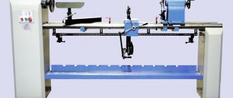
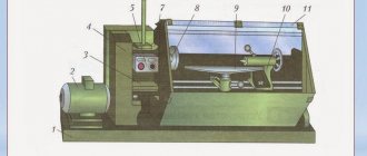
Making cylindrical parts by hand is labor-intensive and time-consuming work. And it is difficult to get a good quality product. It is much faster and more accurate to make a cylindrical part on a lathe. It processes wood blanks by turning. The main parts of a lathe are a bed, a headstock with an electric motor, a tailstock and a tool rest.
Lathe for wood processing STD-120M and its parts: 1 – base; 2 – electric motor; 3 – bed; 4 – belt drive guard (casing); 5 – magnetic starter; 6 – front headstock; 7 – spindle; 8 – tool rest; 9 – tailstock.
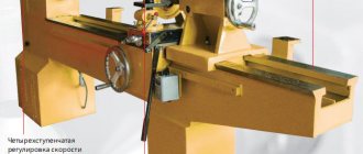
The headstock (see figure) contains a spindle - a shaft that receives rotation from an electric motor using a belt drive, as well as bearings.
1 — headstock body; 2 — belt pulley; 3 — washer with locking screw; 4, 7 — shaped covers; 5 - thrust ring; 6 - spindle; 8 - special nut.
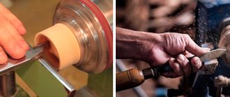
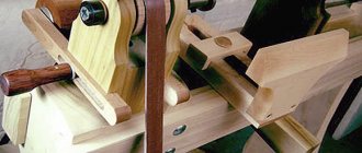
The end of the spindle has a thread; special devices are screwed onto it for fastening the left end of the workpiece. Depending on the size of the workpiece, different devices are used: a trident (see Fig. a), a faceplate (see Fig. b), a cartridge (see Fig. c).
Workpieces of small diameter and length up to 150 mm are fixed in a chuck. Before this, the end of the workpiece is slightly beveled into a cone, clamped in a workbench clamp and driven into the chuck with a mallet. For more reliable fastening, a screw is screwed into the workpiece through the side hole.
Long blanks are secured at one end in a trident. To do this, make a recess in the center of the end of the workpiece with an awl (or drill a hole with a diameter of 4-5 mm to a depth of 5-9 mm). After this, a cut is made through the center of the workpiece with a hacksaw with fine teeth to a depth of 3-5 mm. In the center of the other end, make a recess with an awl.
Short workpieces of large diameter are secured in the faceplate, screwing the workpiece with screws.
The tailstock (see figure) serves as a support for the right end of the long workpieces. The tailstock is brought to the workpiece along the frame guides and secured motionless with a bolt and nut. Finally, the end of the workpiece is pressed with a special part - the center. It is moved by rotating the flywheel and secured with a clamp.
1 - body; 2 — center (Morse cone); 3 - quill; 4 — clamp handle; 5 - hole for lubrication; 6 — quill nut; 7 — quill screw; 8 - threaded bushing; 9 - flywheel; 10 — screw for fastening to the frame; 11 - cracker.
The support for the cutting tool is a tool rest (see figure). It can move both along and across the frame, and is secured by turning the handle.
The tool rest is installed in such a way that its upper supporting part is 2-3 mm above the level of the center line of the machine and is no more than 3 mm away from the workpiece. To check the gap, the workpiece is turned by hand one or two turns.
The transmission of motion in mechanisms and machines is shown by symbols on kinematic diagrams. They depict the parts that are directly involved in the transmission of motion. For clarity, contours of other parts are often given. The kinematic diagram of a lathe is shown in the figure.
You can turn on the lathe and work on it only with the permission of the teacher. Do not place tools and foreign objects on the machine bed. The belt drive parts of the machine must be protected. Do not lean on parts of the lathe. Immediately report any malfunctions in the machine and electrical wiring to the teacher.
Modern factories are equipped with lathes (more complex and productive than those you will work on in a training workshop). They are serviced by woodworking machine operators. In addition to mastering all the techniques of turning on a machine, they must know the properties of wood, the structure of machines, be able to read drawings and diagrams, sharpen a tool, and set up a machine
Working on machines requires accuracy and precision, attentiveness and caution, coordination of hand movements
Purpose of the part
Installing a faceplate on a lathe is done in cases of working with parts that simply cannot be clamped into the chuck. These can be large forgings, flat blanks or irregularly shaped parts. Such a device is indispensable when processing products offset from the spindle axis, as well as products whose side surface may be damaged by the mechanical action of the chuck jaws.
To hold the future part, it is pressed against the plane of the equipment, or fastened using special devices. After installation, it is necessary to align the axis of the material being processed and the spindle, since this method does not provide guaranteed centering.
Faceplates are also used when it is necessary to use non-standard cartridges or devices. In some versions, it is not the materials being processed that are attached to it, but the cutting tool.
Installation features
The pressure meter must only be mounted in a vertical position. This should ensure normal reading of the received data. The meter scale can be tilted at an angle of no more than 30°. The sensor must be illuminated and protected from exposure to sunlight and low temperatures.
After the device is installed and the system is ready for operation in normal mode, then to ensure the safety of the device, it is not advisable to immediately load the installed measuring equipment. It is advisable to increase the pressure gradually, without any jumps and without crossing the established boundaries.
When installing the meter in place, it is necessary to ensure that the connection between the meter and the fitting in which it is mounted is tight. For this, various sealing materials are used, for example, FUM tape or thread. To increase reliability, sealing materials can be treated with a sealant. All materials used must comply with operating conditions, that is, if superheated steam is used in the pipeline system (minimum temperature 130 °C), then installing FUM tape designed for an operating temperature of 95 °C is unacceptable. By the way, some installation organizations, in the old fashioned way, use tow as an insulating material; it should be noted that this is not encouraged.
Criterias of choice
Before buying a device, you need to understand exactly what it is needed for and where it will be installed.
Important selection criteria:
- Measuring range. Rule: the working pressure in the pipeline should be no more than 2/3 of the maximum of the measurement scale, but not less than 1/3. If the pressure in the pipe is 5 atm, then you need to buy a pressure gauge with a scale of 0...10 atm.
- The accuracy class varies from 0.15 to 3. The lower, the more accurate. For a cold or hot water supply system, an accuracy of 1.5% is sufficient.
- The location of the fitting can be radial or end when it is from below; and axial or frontal, when he is behind.
- Operating temperature range.
- Temperature operating conditions.
- Working medium (water, steam, oil and so on);
- Diameter. It should be such that the device fits in the chosen location and the dial is clearly visible.
It is also necessary to pay attention to the connecting thread of the fitting. It can be metric - its parameters are measured in mm, denoted by the letter M, for example M20/1.5, which means the outer diameter is 19.9 mm, the inner diameter is 18.7 mm, pitch 1.5. Domestic manufacturers use it by default
Domestic manufacturers use it by default.
Pipe thread is designated by the letter G. G1/2" means an outer diameter of 20.9 mm, an inner diameter of 18.6, a pitch of 1.8 mm or 14 threads per inch.
The technical passport of a new device must contain a factory verification mark. A verification period of less than a year confirms that the device gives correct readings.
Requirements for faceplates
As has already been said many times above, before being placed on the market, faceplates must undergo certification to certify the buyer that they comply with the standards established by the state. So, for example, faceplates should be:
- Made of cast iron (grade SE20, GOST 1412) or steel (35L, GOST 977);
- They are equipped with a classic circular scale, the division value of which should not exceed 1°;
- Perfectly calibrated and centered. Checks must be carried out regularly using the methods described in regulatory documents.
A complete list of requirements for faceplates is listed in the regulatory document GOST 16935-93, group No. 27.
Requirements for the operation of pressure gauges
The main requirement for the operation of pressure gauges is operator safety.
During operation, it is ensured both by the design of the pressure gauge and by equipping the front surface of the pressure gauge with protective shields or nets (clause 6.2 of GOST 2405-88 “Pressure gauges, vacuum gauges, pressure-vacuum gauges, pressure gauges, draft gauges and draft pressure gauges. General technical conditions”). Pressure gauges and connected to pipelines must be protected from radiant heat and freezing. In some cases, depending on the operating conditions and the properties of the working medium, the pressure gauge may be equipped with a siphon tube, an oil buffer and other devices that protect it from the effects of the environment and temperature. Devices for removing the internal gas medium must not be connected to the connecting line that goes to the pressure gauge. The pressure gauge is installed using a key by screwing it in. When screwing in, it is not allowed to apply force to the pressure gauge body. Pressure gauges must be free from corrosion, contamination, cracks, and damage to the dial and threads. It is necessary to place a three-way valve or device between the vessel and the pressure gauge, which allows the readings to be checked using a control pressure gauge. The pressure gauge is placed and illuminated in such a way that its readings are convenient for maintenance personnel to observe. The diameter of pressure gauge housings installed from the level of the observation platform at a height of up to 2 m must be at least 100 mm, at a height from 2 to 3 m, at least 160 mm, and at a height from 3 to 5 m, at least 250 mm. If the pressure gauge is located at a height of more than 5 m, a backup pressure gauge is installed at a lower elevation. A red line (mark) must be placed on the pressure gauge scale to indicate the maximum permissible pressure, or the pressure gauge is provided with an additional red arrow, the movement of which is not connected with the main working arrow. In this case, drawing a red line on the glass of the device is not allowed. On dials for measuring pressure of oil-hazardous substances, for example, gaseous oxygen, there must be the inscription “Oxygen. Oil hazardous!” It is prohibited to use pressure gauges that have: - no seal or test mark; - broken glass; - there is no red mark on the maximum permissible pressure or an additional (control) red arrow on the scale; - the working arrow does not return to zero scale mark by an amount exceeding half the minimum permissible measurement error for a particular pressure gauge; - there are other damages that may affect the correctness of the pressure gauge readings; - the inspection period has expired. Liquid pressure gauges are allowed to be used at gas pressures up to 0.03 MPa.
{module 43}
To leave a comment, please register or log in to the site.
Installation and use rules
On screw-cutting lathes, faceplates are installed on the headstock spindle. And in rotary lathes, the faceplates are part of large rotary tables.
On universal lathes
Jaw chucks are considered universal, as they have a large number of varieties and jaws, but despite this, not all parts can be simply fixed in the chuck. Such parts can be levers, connecting rods, etc., which are not symmetrical. It is for such parts that faceplates are used.
Parts are usually fixed using bolts or cams. Uneven parts are secured with a clamp in the center. If the part needs to be attached relative to the axis, low shims may be needed to raise the bar. The pads must be equal to the walls of the part. To prevent the part from falling out, the strips must be at the level of the faceplate.
Usually a counterweight is included with the faceplate. If it is not installed, the machine will vibrate, causing the part to last less. If the balancing does not change position after stopping, then all calculations were made correctly.
For rotary lathes
Unlike the faceplates of a universal machine, on them they are an additional fastener, while, like on a rotary lathe, they are the main fastener. On rotary lathes, the faceplates are a rotating table.
It looks like a large disk and has a central mount and a sleeve for attaching parts. The bushings of such faceplates quickly fail, but they can be easily replaced without harm to the faceplate itself. Several T-shaped slots extend from the center, in which there are parts for fastening.
In addition to the disk, the faceplate has a very complex structure at the bottom. In the center of the structure there is a hole for the spindle. Bolts are used to secure parts. The design also has: stiffening ribs, guides, and sometimes it is modified by adding a few more guides.
Do it yourself
To understand how hand tools for woodworking are made, let's look at the manufacturing process of several of their main varieties.
Meysel
This is the main tool used for finishing wood workpieces. In skillful hands, this chisel is enough to create any pattern.
A straight-sharpened meisel is ideal for creating rectangular notches in a workpiece. Its width varies from 4 to 40 mm, the standard sharpening angle is from 22 to 45. The required blade slope is determined by the personal preferences of the master over time.
How to make it:
- We take an old file or any other flat rectangular piece. If necessary, align the working end;
- We grind the cutting part, carrying out primary turning. We use an abrasive wheel, making sure that the blade is processed evenly in thickness without differences;
- We harden if the metal is not hard enough;
- We put the handle.
This type of chisel is easy to prepare and can be used to start creating your own collection of hand tools to gain experience and understand the process.
The Meisel with a beveled blade is more versatile than its counterpart:
- It becomes possible to process round products;
- An obtuse angle is suitable for creating roundings;
- The tool is convenient for processing the end of a product.
Manufacturing is similar to the previous device:
- The blank part is processed to the shape of the future tool;
- The chisel is sharpened at an angle of 70-75, after which the tool must be sharpened.
- We attach the handle. Meisel is ready.
Using a similar algorithm, the remaining angular cutters for a wood lathe are created. Sharpening is carried out only after careful control of the tool dimensions.
Maintaining exact angles when making tools yourself is not necessary. It is enough to adhere to the necessary and convenient proportions and evenness of processing.
Semicircle
The semicircular tip of the chisels allows you to create neat notches when processing a wooden product. To make such a cutter, we mark on the workpiece the outline of the tool along which we cut. After this, we sharpen it at an angle of 25...40 in the usual way.
The radius of the chisel affects the size of the recess in the product, therefore for professional production it is advisable to make several cutters with a semicircular tip for different cases.
Groove
After stripping the bark, the wooden trunk is processed with grooved chisels; they are intended for the initial rough finishing of the material and creating a blank for the product.
In addition, grooves are used to cut concave shapes and recesses in frontal turning.
How to make a groove cutter:
- Take a tap to cut a thread of the required diameter.
- We process the metal blank with it at a distance of up to 8-10 cm from the edge, actually cutting off half of the rough product.
- We sharpen the lower convex part of the blade at an angle of 30-40.
Grooved homemade wood turning tools are not easy to make, but it is quite possible to understand the process.
Make or buy
The process of creating tools for working with wood is a fascinating and not always easy task. If you have the right set of tools, an inexperienced person will not have any problems - the process is intuitive, but painstaking.
Of course, you can buy a ready-made set of devices, but how much will it cost... At the same time, the wear of the metal increases over time and even brand new chisels will soon require turning. Own production is a way to get a tool under your own hands. Designer cutters with individual sizes will be adapted to the owner and his needs.
A more detailed description of the chisel making process is presented in the video. The master talks in detail about creating a workpiece, applying sharpening and touches on other important points that are necessary for the successful completion of the work.